In high-speed, high-density electronic systems, micro coaxial cableis often the critical link that determines whether your product performs reliably in the field or fails during EMI/EMC testing.
At FRS, we design and manufacture high-performance micro coaxial cable assembliesthat combine compact size, excellent signal integrity, and robust EMI shielding. This guide explains what makes micro coax the right interconnect for your most demanding applications and how to choose and design with it successfully.
🎯 What Is a Micro Coaxial Cable?
A micro coaxial cableis a miniaturized version of a standard coaxial cable, featuring a center conductor, dielectric insulation, shielding, and an outer jacket.
- Structure: Each conductor is surrounded by its own shield, creating a complete coaxial structure for every signal line.
- Size: The outer diameter is typically 0.3–1.0 mm, allowing for dense routing in tight spaces.
- Shielding: Each core has a dedicated shield, and the overall bundle can have an additional layer, providing superior EMI protection compared to multi-core cables or FFC/FPC.
- Impedance: It is designed for precise, consistent impedance, commonly 50 Ω(single-ended) or 100 Ω(differential), which is essential for high-speed data transmission.
In short:A micro coaxial cable is a high-performance, shielded interconnect optimized for high-speed, high-frequency, and high-densityapplications.
💡 Why Use Micro Coaxial Cable Instead of Standard Cables?
1. Superior Signal Integrity
- Controlled Impedance: Maintains a stable impedance (e.g., 100 Ω differential for MIPI, USB, HDMI) to minimize reflections and signal distortion.
- Low Loss: Employs low-loss dielectrics (like PTFE/FEP) and finely stranded conductors to reduce attenuation, even at multi-gigabit frequencies.
- Reduced Crosstalk: The individual shielding of each core significantly lowers crosstalk compared to unshielded multi-core or ribbon cables.
2. Excellent EMI Shielding
- Individual Shielding: Each core is shielded, preventing interference between adjacent signals.
- Overall Shielding: A braided shield and/or foil over the entire bundle provides robust protection against external EMI/RFI.
- 360° Grounding: Proper termination of the shield to the connector backshell ensures a continuous RF ground path, which is vital for passing EMC tests.
3. Space and Weight Savings
- Miniaturization: Its small diameter allows for routing in extremely confined spaces, such as within hinges or along moving parts.
- Lightweight: Replacing bulky multi-pair cables with micro coax bundles reduces overall system weight—a critical factor in aerospace and UAV applications.
4. Mechanical Flexibility
- Controlled Bend Radius: Designed to be flexed within specified limits without damaging the shielding or dielectric, making it suitable for movable assemblies.
- Durability: High-quality constructions can withstand thousands of flex cycles, which is essential for cable tracks and robotic arms.
5. High Data Rate Capability
- Multi-Gigabit Performance: A single micro coax can reliably support 5–10 Gbps(USB 3.x). With advanced designs, performance can reach 20–40 Gbpsper channel for protocols like USB4, PCIe, and high-speed MIPI.
🔬 How Micro Coaxial Cable Achieves High Performance
1. Conductor and Stranding
- High-Purity Copper: Silver-plated or tinned copper is used to reduce resistance and skin-effect losses at high frequencies.
- Stranding: Fine stranding provides the necessary flexibility while maintaining conductivity.
2. Dielectric Material
- Low-Loss Dielectrics: Materials like PTFE, FEP, or foamed PEare chosen for their low dielectric constant (εr) and low dissipation factor (Df), which minimizes signal loss at high frequencies.
3. Shielding Architecture
- Dual-Layer Shielding: A combination of aluminum foil(for 100% coverage) and a tinned copper braid(for flexibility and low resistance) is common.
- Cable Bundles: For multi-pair assemblies, an additional overall braid or foil wrap provides another layer of isolation.
4. Connector and Termination
- Precision-Made: Micro coaxial connectors (e.g., I-PEX CABLINE®, Hirose, JAE) are designed for minimal stubs and precise impedance matching.
- Controlled Impedance: The transition from the cable to the connector must be smooth to avoid signal reflections. FRS uses automated, high-precision termination to ensure this.
📊 Key Performance Parameters
When evaluating a high-speed, EMI-shielded micro coaxial cable, focus on these critical specs:
- Impedance: Match your system (e.g., 50 Ωfor RF, 75 Ωfor video, 100 Ωdifferential for LVDS/MIPI). Mismatches cause reflections and signal integrity issues.
- Attenuation (Insertion Loss): The signal loss per unit length (dB/m). It increases with frequency, so check loss at your operating frequency (e.g., 1 GHz, 5 GHz, 10 GHz).
- Return Loss & VSWR: Measure how well the cable is impedance-matched. Poor return loss leads to an “eye diagram closure” and higher bit error rates (BER).
- Shielding Effectiveness: Expressed in dB, this indicates how well the cable blocks external noise and contains its own emissions. Look for cables with high shielding effectiveness at your operating frequency.
- Operating Frequency Range: Ensure the cable is specified to cover your entire operating range with acceptable loss. Micro coax can operate from DC to 40 GHz+, depending on the design.
- Temperature Rating: Verify the cable can withstand your application’s environment. FRS cables offer standard ratings like -20°C to +80°C, with options for extended ranges.
- Flex Life & Bend Radius: For moving applications, check the minimum bend radius and rated flex cycles. This is crucial for hinges, robotic arms, and medical devices.
🔌 Common Micro Coaxial Connector Types
The performance of your micro coaxial cable assemblyis only as good as its connection. Here are the main connector families:
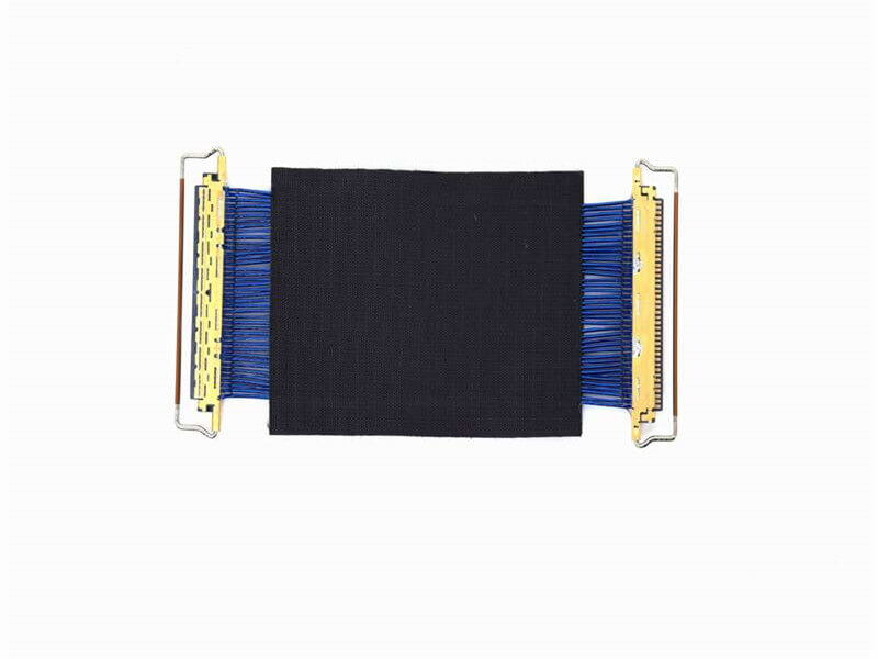
- Board-to-Board (BTB) Micro-Coax Connectors: Used for high-density connections between PCBs, common in laptops and medical devices.
- FPC/FFC-to-Board Connectors: Often used with micro coax jumpers for LCD/display and camera module interconnects.
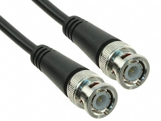
- RF/Microwave Micro-Coax Connectors: Includes SMA, SMB, and MMCX types for test equipment and wireless systems. FRS offers models like a 0.81 mm, 50 Ω micro coax with an SMA connector, rated for 0–3 GHz.
- Custom LVDS/High-Speed Display Connectors: Used in high-resolution displays and industrial monitors. FRS provides custom LVDS cable assemblies for stable, low-EMI video transmission.
🏭 FRS Micro Coaxial Cable: Built for Performance
FRS is a specialist in micro coaxial cableand high-speed cable assemblies, with deep experience in RF, microwave, video, and high-speed digitalinterconnects.
1. Product Examples
- 0.81 mm Micro Coax Assembly: A prime example of a high-speed, EMI-shielded micro coaxial cable. It features a 50 Ωimpedance, an operating frequency of 0–3 GHz, and a durable PVC jacket. Ideal for wireless, telecom, and aerospace applications.
- LVDS / High-Speed Video Cable Assemblies: FRS manufactures custom LVDS cables for industrial, medical, and military applications, ensuring stable signal transmission and low EMI.
2. Manufacturing & Quality
- Automated Production: FRS utilizes advanced equipment for high-precision extrusion, shielding, and termination to ensure consistency and performance.
- Rigorous Testing: Every cable assembly undergoes 100% electrical testing for continuity, insulation resistance, and high-voltage performance.
- Certifications: FRS products are manufactured in compliance with RoHS and REACHstandards, ensuring they are environmentally responsible.
3. Customization Capabilities
FRS provides comprehensive OEM/ODM servicesto meet your exact needs:
- Cable: Diameter, impedance, shielding, and jacketing.
- Connectors: Type, plating, and pinout.
- Performance: Custom designs for specific frequency, temperature, or flex-life requirements.
🎯 Key Application Areas
1. Telecom & Wireless Infrastructure
Micro coax is used in 5G/6G backhaul, microwave links, and satellite systems where low loss and high shieldingare critical. FRS’s 0.81 mm cable is a proven solution for these applications.
2. High-Speed Video & Display
For LVDS, eDP, HDMI, and DisplayPort, micro coax ensures signal integrity over long distances. FRS’s LVDS cable assemblies are trusted in industrial and medical displays.
3. Medical & Healthcare
In devices like endoscopes and patient monitors, miniaturization, biocompatibility, and reliabilityare paramount. FRS provides custom micro coax solutions that meet these stringent demands.
4. Aerospace, Military & Automotive
These sectors require cables that perform in extreme conditions. FRS offers ruggedized micro coax assemblies for avionics, defense, and automotive systems, including ADAS and in-vehicle infotainment.
5. Industrial & Test Equipment
For applications like machine vision and automated test equipment (ATE), FRS provides high-flex micro coax harnesses that maintain signal integrity in dynamic environments.
🛠️ How to Select the Right Micro Coaxial Cable
1. Define Your Key Parameters
- Signal Type & Data Rate: Is it analog RF, high-speed digital (e.g., 5 Gbps USB 3.0), or video (e.g., LVDS)?
- Frequency Range: What is the maximum operating frequency?
- Required Cable Length: Longer cables have higher loss.
- Impedance: Match your system (50 Ω, 75 Ω, or 100 Ω differential).
- Environmental Conditions: Consider temperature, moisture, chemicals, and mechanical stress.
2. Evaluate Cable Specifications
- Attenuation vs. Frequency: Ensure the loss at your max frequency is within acceptable limits.
- Shielding Effectiveness: For noisy environments, prioritize cables with high shielding effectiveness.
- Mechanical Properties: Check the bend radius and flex life if the cable will move.
3. Choose the Right Connector
- Match the Interface: Select a connector that is compatible with your PCB footprint and mating hardware.
- Ensure Impedance Continuity: The connector must be designed to maintain the cable’s characteristic impedance.
- Consider Shielding: Some connectors offer integrated EMI shielding features for enhanced performance.
4. Prototype and Test
- Build Samples: Work with a supplier like FRS to create prototype assemblies.
- Perform SI/PI Analysis: Simulate the channel to identify potential issues.
- Run EMI/EMC Tests: Validate the design in a certified lab to ensure it meets all regulatory requirements.
🤝 Partner with FRS for Your Next Project
FRS is your strategic partner for high-speed, EMI-shielded micro coaxial cablesolutions. Our expertise in RF/microwave, video, and high-speed digital interconnectsensures your product performs reliably in the most demanding applications.
Contact FRS todayto discuss your project requirements and discover how our custom micro coaxial cable assemblies can help you achieve your design goals.
In an era where reliable signal transmission and safety are paramount across industries, coaxial cable manufacturers have prioritized advancements in safety performance. This article explores the latest upgrades in coaxial cable technology, focusing on enhanced fire resistance, electromagnetic interference (EMI) protection, and environmental durability—all critical for applications ranging from 5G infrastructure to industrial automation.
1. Fire Resistance Redefined
One of the most significant safety improvements lies in fire-resistant designs. Traditional coaxial cables often relied on polyethylene or PVC sheaths, which posed risks of rapid flame spread and toxic smoke release . Modern solutions now integrate polymer composites like PTFE (polytetrafluoroethylene) and FEP (fluorinated ethylene propylene), which exhibit self-extinguishing properties and minimal smoke emission. For example, a patented design introduces a PTFE microporous film between the dielectric layer and outer conductor, effectively delaying structural collapse during fires while maintaining signal integrity . This innovation aligns with international standards such as GB31247-2014 and UL 444-2023, ensuring compliance with rigorous fire safety requirements for both indoor and outdoor installations .
2. Enhanced EMI Shielding for Reliable Signals
EMI remains a persistent challenge in high-frequency applications. New coaxial cables feature multi-layer shielding architectures, combining aluminum braids (up to 77% coverage) with conductive tapes to achieve shielding effectiveness exceeding 90 dB across wide frequency ranges . For instance, Channel Master’s Coax+ employs a tri-shield design that outperforms quad-shield cables in long-term testing, reducing signal loss by up to 30% compared to conventional models . This is particularly critical in environments with dense electromagnetic activity, such as data centers or near power lines, where interference can corrupt video, audio, or control signals.
3. Extreme Environment Resilience
Coaxial cables now withstand harsher conditions than ever. Innovations in materials science enable operation across -104°C to +165°C while resisting moisture, UV radiation, and chemical exposure . Cicoil’s high-temperature cables, for example, use Flexx-Sil™ jackets that maintain flexibility and dielectric stability even after 6,500 hours at 160°C . Similarly, FRS’s CELLFLEX® Lite series, with a corrugated aluminum outer conductor, offers superior resistance to corrosion and mechanical stress, making it ideal for outdoor 5G base stations and maritime applications .
4. 5G-Ready Performance
With the rollout of 5G, coaxial cables must support higher frequencies (up to 3.8 GHz) and stricter phase stability requirements. FRS’s Radiaflex series addresses this by integrating mode suppression technology, eliminating stop-bands and ensuring seamless connectivity in tunnel deployments . These cables also comply with 3GPP standards, delivering low insertion loss and high power handling—critical for mission-critical networks like smart transportation systems .
5. Rigorous Testing and Compliance
Manufacturers now subject coaxial cables to comprehensive testing protocols. For example, FRS’s 5G radiating cables undergo China Academy of Telecommunication Technology (CTTL) certification, validating their performance in extreme conditions . Key metrics include:
- Structural return loss: Ensuring impedance uniformity to minimize signal reflections .
- Phase stability: Maintaining signal coherence across temperature fluctuations .
- Flame propagation: Meeting IEC 60332-3 Class A standards for vertical burn resistance .
Why These Upgrades Matter
The safety advancements in coaxial cables directly translate to:
- Reduced downtime: Reliable performance in fire-prone or high-interference environments.
- Cost savings: Longer lifespan and lower maintenance due to improved durability.
- Compliance confidence: Alignment with global safety and environmental regulations.
FRS: Leading the Charge in Safe, High-Performance Coaxial Cables
When it comes to cutting-edge coaxial solutions, FRS stands out with its innovative product lines.
Key Offerings:
- CELLFLEX® Lite Series
- Aluminum-based design: Lighter than copper cables (20% weight reduction) yet equally durable, with a corrosion-resistant corrugated outer conductor .
- Universal compatibility: Uses the same connectors as traditional copper cables, simplifying retrofitting .
- Fire safety: Compliant with UL 94 V-0 and IEC 60332-3 standards, ensuring minimal flame spread .
- Radiaflex 5G Radiating Cables
- Ultra-broadband support: Covers all 3GPP bands up to 3.8 GHz, future-proofing investments .
- Tunnel-specific performance: Uniform signal distribution in confined spaces, critical for smart rail and metro systems .
- FSD High-Frequency Cables
- Low attenuation: Achieves 30% less signal loss than traditional semi-rigid cables, ideal for test equipment and aerospace applications .
- Extreme shielding: Shielding effectiveness >165 dB, ensuring interference-free operation in high-risk environments .
Why Choose FRS?
- Proven reliability: Over a decade of field-tested performance in mission-critical projects like the Eurotunnel and Norwegian railway systems .
- Sustainability: Lightweight designs reduce carbon footprints, while recyclable materials align with eco-friendly goals.
- Technical expertise: Dedicated R&D teams ensure products meet the latest industry standards and emerging 5G/6G demands.
Conclusion
The upgraded safety performance of modern coaxial cables reflects a commitment to reliability, durability, and compliance. Whether in 5G networks, industrial settings, or extreme environments, these innovations ensure seamless operation while mitigating risks. For businesses seeking the best-in-class solutions, FRS’s comprehensive range of coaxial cables combines cutting-edge technology with unmatched safety—a testament to their leadership in the industry.
Micro coaxial cables – those incredibly thin wires inside your smartphone, drone, medical device, or advanced camera – are engineering marvels. But precisely because they’re so small, they’re prone to specific types of damage that can cripple your device’s performance. Understanding these common failure modes is crucial for preventing headaches, costly repairs, or even dangerous malfunctions.
Why Should You Care About Micro Coax Failure?
When a micro coax cable fails, the signals it carries – crucial data, video, or control signals – become corrupted or disappear entirely. This translates to frustrating problems: grainy video feeds, dropped connections, malfunctioning sensors, or a complete device shutdown. Knowing how they fail is the first step to preventing it.
The Usual Suspects: Most Common Micro Coax Failure Modes
- Mechanical Stress & Fatigue (The Bending and Pulling Problem):
- What Happens: Constant bending, twisting, pulling, or exceeding the cable’s minimum bend radius puts immense stress on the tiny internal components – the fragile center conductor and the delicate dielectric insulator surrounding it.
- The Failure: This repeated stress can lead to:
- Center Conductor Break: The thin inner wire snaps.
- Conductor Fatigue: Metal weakens and cracks over time.
- Insulator/Dialectic Damage: The plastic layer crushes or cracks, changing signal properties.
- Shielding Damage: Braided or foil shielding tears, allowing noise in or signal leakage out.
- Symptoms: Intermittent signal, complete signal loss, increased noise, signal degradation only when the cable is flexed.
- Cause: Poor routing during installation, inadequate strain relief, sharp bends at connectors, repetitive motion in use.
- Connector/Interface Failures (The Weak Link):
- What Happens: The point where the tiny cable attaches to a connector (like a micro U.FL or MMCX) is inherently vulnerable. Soldering or crimping these connections requires precision. Mechanical stress is often concentrated here.
- The Failure:
- Poor Solder/Crimp Joints: Weak connections cause signal loss or dropouts.
- Lifted Pads/Traces: The tiny metal pad on the circuit board that the connector mounts to can crack or lift off due to stress or heat.
- Broken Center Pin: The extremely fine center pin in micro connectors can bend or break.
- Contamination/Corrosion: Dirt, flux residue, or moisture cause poor connections.
- Symptoms: Intermittent connection, poor signal quality, no signal, connection fails if connector is wiggled.
- Cause: Improper installation technique, excessive force during mating/unmating, poor solder/crimp quality, insufficient strain relief at the connector boot.
- Kinking or Crushing (The Pinch Point):
- What Happens: Accidentally pinching the cable between surfaces (like a device case), running it over sharp edges, or crushing it under components permanently deforms it.
- The Failure: Deformation flattens the cable, drastically altering its carefully designed geometry. The center conductor can shift towards the shielding or become damaged. Dielectric properties change.
- Symptoms: Significant signal loss, increased reflections, unpredictable signal behaviour, potential intermittent connections.
- Cause: Poor routing during assembly/maintenance, lack of cable management, inadequate protection around chassis openings.
- Environmental Degradation (Heat, Moisture, Chemicals):
- What Happens: Exposure to extreme temperatures, humidity, solvents, oils, or corrosive elements degrades cable materials over time.
- The Failure:
- Insulation/Cable Jacket Deterioration: Plastics become brittle and crack, or soft and sticky.
- Shielding Corrosion: Moisture ingress corrodes copper shielding.
- Conductor Oxidation/Corrosion: Moisture or chemicals attack the center conductor.
- Material Breakdown: Dielectric properties change with temperature extremes.
- Symptoms: Increased signal loss over time, intermittent faults due to cracks/moisture, shorts, visible damage to cable jacket.
- Cause: Operating outside cable specifications, use in harsh environments without appropriate protection or cable grade (e.g., non-military-spec cable exposed to salt spray).
- Phase Instability (Where Precision Matters):
- What Happens: In high-frequency, precision applications (like phased arrays, radar, high-speed digital), the phase relationship between signals on different cables is critical. Even tiny physical changes affect this.
- The Failure: Mechanical stress or environmental changes (mainly temperature fluctuations) cause the cable’s electrical length to change slightly. This disrupts the phase timing between signals.
- Symptoms: Degraded system performance (e.g., lower data throughput, inaccurate positioning, poor beam forming), increased bit errors.
- Cause: Inadequate phase stability specification for the application, thermal cycling, mechanical strain affecting the cable assembly.
Preventing Failure: How to Keep Your Micro Coax Reliable
Knowing the pitfalls is half the battle. Here’s how to win the other half:
- Handle with Extreme Care: Treat micro coax like fine jewelry. Avoid sharp bends, pinching, twisting, and excessive pulling. Always respect the Minimum Bend Radius!
- Master Connector Installation: Use proper tools and techniques. If soldering, control heat carefully. If crimping, use the correct tooling. Ensure adequate, well-designed strain relief where the cable meets the connector.
- Route with Purpose: Plan cable paths meticulously. Avoid sharp edges, pinch points, and areas of high flex or movement. Use cable ties loosely (avoid overtightening!) and guides to secure them safely.
- Choose the Right Cable & Connector: Match the cable specifications (impedance, loss, phase stability, bend radius, environmental rating) to your application’s demands. Don’t underspecify.
- Mind the Environment: If operating in harsh conditions (heat, cold, moisture, chemicals), select cables with appropriate jacketing (e.g., PTFE, FEP, Military Spec ratings) and ensure seals are adequate.
- Consider Manufacturing Quality: Purchase cables and connectors from reputable manufacturers adhering to industry standards (like IPC). Poorly made connectors or inconsistent cable construction are inherent failure points.
- Train Technicians: Ensure anyone handling or installing micro coax understands the delicacy and specific procedures involved.
Conclusion: Reliability Starts with Awareness
Micro coax cables are essential but fragile links in modern electronics. By understanding the most common ways they fail – mechanical stress at connectors, kinking, exceeding bend radius, and environmental exposure – you can take proactive steps to prevent these issues. Careful handling, correct installation, mindful routing, and selecting the appropriate cable and connector for the job are paramount. Investing this effort upfront translates directly to increased reliability, reduced downtime, and devices that perform as intended for their entire lifespan.
Related articles:
- Understanding Micro Coax Impedance: Why 50 Ohms?
- Micro Coax Connectors: A Guide to U.FL, MMCX, and More
- How to Strip and Terminate Micro Coax Cables Safely
- Choosing the Right RF Cable for Harsh Environments
- Testing Micro Coax Cables: VSWR and Insertion Loss Explained
Introduction: The Need for Speed at the Edge
Edge computing is revolutionizing how we process data. By bringing computation closer to where data is generated – sensors, IoT devices, cameras, machines – it slashes the time wasted sending everything back to a distant cloud data center. This is crucial for applications demanding real-time responses: think autonomous vehicles making split-second decisions, factories optimizing production lines instantly, surgeons using AR during operations, or smart cities managing traffic flow dynamically.
The core promise of edge computing is ultra-low latency. But achieving this isn’t just about placing a server nearby. The physical connections between the sensors, devices, and the edge server itself are critical bottlenecks. This is where micro-coaxial cables emerge as a surprisingly powerful, yet often overlooked, solution.
The Latency Culprit: Traditional Cabling Limitations
Many edge deployments initially rely on familiar cabling:
- Standard Twisted Pair (e.g., Ethernet Cat5e/6): While cost-effective and widely used, they have limitations in bandwidth and susceptibility to electromagnetic interference (EMI), especially over longer runs common in industrial settings. Signal degradation can lead to errors and retransmissions, increasing latency.
- Fiber Optic: Offers immense bandwidth and immunity to EMI, making it excellent for long-distance backbone connections. However, fiber can be more expensive, requires specialized termination tools and skills, and is less flexible for tight spaces or frequent reconfigurations common at the edge.
Enter Micro-Coaxial Cable: The Low-Latency Enabler
Micro-coaxial cable (often called “micro-coax”) is a specialized type of coaxial cable designed for high-frequency signals in compact spaces. Think of it as a miniature version of the cable connecting your TV, but engineered for demanding data transmission.
- Structure: It features a central conductor surrounded by a dielectric insulator, a metallic shield (often multiple layers – braid and foil), and an outer protective jacket. This design is key to its performance.
- Key Advantages for Edge Latency:
- Superior Signal Integrity & Shielding: The robust shielding effectively blocks external EMI/RFI noise and prevents the cable’s own signal from radiating out. This results in cleaner signals, fewer errors, and less need for data retransmission – a direct win for reducing latency.
- High Bandwidth Capability: Micro-coax is engineered to carry high-frequency signals with minimal loss (attenuation). This translates to support for very high data rates over relatively short distances (perfect for edge device-to-gateway or gateway-to-edge-server links), ensuring data packets move quickly.
- Low Signal Attenuation: Compared to twisted pair, micro-coax experiences less signal weakening over distance at high frequencies. This means stronger signals arrive at the destination, reducing the need for signal boosting and potential latency-inducing processing.
- Flexibility & Miniaturization: True to its name, micro-coax is incredibly small and flexible. This makes it ideal for routing through tight spaces within machinery, robotics, sensor clusters, or compact edge enclosures where space is at a premium. Its flexibility also aids in installation and maintenance.
- Durability: High-quality micro-coax is built to withstand the rigors of industrial environments – vibration, temperature fluctuations, and minor physical stresses – ensuring reliable, long-term performance critical for continuous edge operations.
How Micro-Coax Specifically Tackles Edge Latency
- Minimizing Transmission Errors: By providing a clean, noise-free transmission path, micro-coax drastically reduces bit errors. Fewer errors mean fewer packets need to be resent, eliminating the significant latency penalty associated with retransmissions.
- Enabling Higher Data Rates: Its ability to handle high frequencies allows micro-coax to support the latest high-speed interfaces (like USB 3.x/4, Thunderbolt, high-speed serial links) directly connecting sensors, cameras, and devices to edge processing units. Faster raw data transfer directly lowers latency.
- Reducing Processing Overhead: Cleaner signals mean the receiving device (edge server, gateway) spends less computational power on error correction and signal conditioning. This frees up valuable CPU/GPU resources for the actual application processing, contributing to lower overall response time.
- Facilitating Dense Deployments: Its small size allows for routing multiple cables in tight bundles without significant crosstalk (thanks to the shielding), enabling dense sensor networks or device clusters feeding into an edge node efficiently.
Practical Latency Reduction Strategies Using Micro-Coax
- Identify High-Speed, Sensitive Links: Focus deployment on connections where latency is most critical and EMI is likely high. Examples:
- High-resolution industrial cameras to vision processing units.
- Critical sensor arrays (vibration, temperature) on manufacturing lines.
- LiDAR/Radar sensors on autonomous vehicles/robots to the local compute module.
- High-bandwidth medical imaging devices to an edge server in a hospital.
- Connections within a crowded industrial control cabinet.
- Replace Problematic Twisted Pair Runs: If experiencing latency spikes or instability on existing copper links (especially longer runs or in noisy environments), strategically replacing them with micro-coax can yield significant improvements.
- Utilize for Internal Edge Device Wiring: When designing custom edge devices or gateways, use micro-coax internally for high-speed board-to-board connections or to interface with high-frequency modules, minimizing internal signal delays and noise.
- Ensure Proper Installation:
- Termination: Use high-quality connectors and ensure proper termination techniques (soldering or crimping) specific to micro-coax to maintain impedance and shielding integrity. Poor termination is a major source of failure.
- Grounding: Ensure the cable shield is properly grounded at one end (usually the receiving end) to prevent ground loops while maintaining noise protection. Follow equipment manufacturer guidelines.
- Bending Radius: Respect the minimum bend radius specified for the cable to avoid damaging the delicate internal structure and degrading performance.
- Strain Relief: Secure cables near connectors to prevent stress on the termination points.
Micro-Coax vs. Fiber: Choosing Wisely
Micro-coax excels in short-range, high-density, high-flexibility, and cost-sensitive edge applications where distances are typically under 10-30 meters. Fiber remains superior for long-distance backbone links (connecting edge nodes back to aggregation points or core networks) where its bandwidth and noise immunity over kilometers are unmatched. Often, the optimal solution uses micro-coax for the “last meter” device connections and fiber for the “last mile” backhaul.
Conclusion: Unlock Faster Edge Performance
Achieving the ultra-low latency promise of edge computing requires attention to every link in the chain. While processors and software get much of the focus, the physical cabling is a fundamental factor. Micro-coaxial cables, with their superior shielding, high bandwidth, low loss, and compact flexibility, offer a highly effective and practical solution for reducing latency in critical edge connections.
By strategically deploying micro-coax in high-noise environments, for high-speed sensor/device links, and within compact edge devices, you can significantly minimize transmission errors, enable faster data transfer, and free up processing resources. This translates directly into more responsive, reliable, and efficient edge applications – whether it’s enabling safer autonomous systems, optimizing smart factories, or powering immersive real-time experiences. Don’t let your cabling be the bottleneck; consider micro-coax as a key tool in your edge latency reduction strategy.
Ready to explore micro-coaxial solutions for your edge deployment? Consult with connectivity specialists to find the right cable specifications and connectors for your specific bandwidth, environmental, and space requirements.
In the vast expanse of modern satellite communications, where signals need to traverse incredible distances with utmost precision, micro – coaxial cables have emerged as a crucial component. These cables, smaller in diameter compared to their conventional counterparts, play a pivotal role in ensuring seamless communication between satellites and ground stations.
Understanding Micro – Coaxial Cables
Micro – coaxial cables, often referred to as micro – coax, are designed with a focus on miniaturization without sacrificing performance. They typically have an outer diameter of 1 mm or less, making them highly suitable for applications where space is at a premium, such as in satellite equipment.
Structure
The basic structure of a micro – coaxial cable is similar to that of a standard coaxial cable. It consists of a center conductor, which is responsible for carrying the electrical signal. This is usually made of high – conductivity materials like copper or a copper alloy. Surrounding the center conductor is an insulating dielectric layer. Materials such as polyethylene (PE) or polytetrafluoroethylene (PTFE) are commonly used for this layer. The dielectric helps to isolate the signal in the center conductor and also affects the cable’s electrical properties, such as impedance.
The outer conductor, often in the form of a braided metal shield or a metal foil, provides electromagnetic shielding. This shielding is essential as it protects the signal in the center conductor from external electromagnetic interference (EMI). Finally, an outer jacket made of materials like polyvinyl chloride (PVC) or fluoropolymers covers the entire cable, providing mechanical protection and environmental resistance.
Connector Compatibility
Due to their small size, micro – coaxial cables use specialized connectors. Connectors like the u.fl (developed by Hirose Electric Group), mhf (by I – Pex), and amc (by Amphenol) are commonly used. These connectors are designed to mate with the small – diameter cables and ensure a reliable connection. They are also engineered to maintain the electrical characteristics of the cable, such as impedance, at the connection point.
Advantages of Micro – Coaxial Cables in Satellite Communications
High – Speed Signal Transmission

Satellite communications demand the rapid transfer of large amounts of data. Micro – coaxial cables are well – equipped to handle this requirement. They offer high – speed signal transmission capabilities due to several factors. Firstly, the design of the cable, with its matched and stabilized impedance between the inner conductor, dielectric, and outer conductor, results in low return loss. Return loss is the amount of signal that is reflected back towards the source instead of being transmitted forward. By minimizing return loss, more of the signal power is transmitted, ensuring efficient data transfer.
Secondly, for a given impedance, micro – coaxial cables often have a relatively large cross – sectional area of the inner conductor. This reduces the insertion loss, which is the loss of signal power as the signal travels through the cable. The combination of low return loss and insertion loss allows micro – coaxial cables to support high – speed data rates, which are essential for applications such as high – definition video transmission from satellites for Earth observation or real – time communication for satellite – based internet services.
Exceptional Flexibility
Satellites are complex pieces of machinery with a limited amount of space and often require cables that can be routed in tight spaces. Micro – coaxial cables are highly flexible. Their flexibility allows them to be bent around various components within the satellite without significant degradation of their electrical characteristics. This is crucial for applications where the cable may need to be moved or adjusted during the satellite’s assembly or operation. For example, in satellites with deployable antennas, the micro – coaxial cables connecting the antenna to the transceiver need to be flexible enough to accommodate the movement of the antenna without causing signal disruptions.
Excellent Electromagnetic Shielding
In the harsh environment of space, satellites are bombarded with various forms of electromagnetic radiation. Additionally, there is a need to prevent interference between different electronic components within the satellite. Micro – coaxial cables’ outer conductor, which acts as a shield, provides excellent protection against external electromagnetic interference. This shielding ensures that the signals transmitted through the center conductor remain pure and unaffected by external noise. It also helps in preventing the cable from radiating its own electromagnetic energy, which could potentially interfere with other sensitive equipment on the satellite.
Applications of Micro – Coaxial Cables in Satellite Systems
Satellite – to – Ground Communication Links
The link between a satellite and a ground station is the backbone of satellite communication. Micro – coaxial cables are used extensively in the satellite’s communication payload. They connect the various components of the transceiver, such as the power amplifier, low – noise amplifier, and the antenna feed. The high – speed signal transmission and low – loss characteristics of micro – coaxial cables ensure that the signals sent from the satellite to the ground are strong and accurate. Similarly, on the ground station side, micro – coaxial cables are used in the receiving and transmitting equipment to connect different modules and ensure efficient signal processing.
Intra – Satellite Communication
Satellites are composed of multiple subsystems, such as the power generation system, attitude control system, and data processing system. These subsystems need to communicate with each other. Micro – coaxial cables are used to establish these intra – satellite communication links. For example, the data from the satellite’s sensors, which monitor various parameters like temperature, pressure, and orientation, need to be transmitted to the data processing unit. Micro – coaxial cables provide a reliable and space – saving solution for this data transfer. Their flexibility also allows for easy integration into the complex wiring systems within the satellite.
Payload Instrumentation
Satellites carry a variety of payloads for different purposes, such as Earth observation cameras, spectrometers, and communication relays. Micro – coaxial cables are used to connect the sensors and actuators within these payloads. In an Earth observation satellite’s camera system, for instance, micro – coaxial cables are used to transfer the high – resolution image data from the camera sensor to the data storage and transmission units. The small size and high – performance capabilities of micro – coaxial cables make them ideal for such applications where precise signal transfer is required in a compact space.
Challenges and Solutions in Using Micro – Coaxial Cables for Satellite Communications
Radiation Resistance
Space is a radiation – intensive environment. High – energy particles from the sun and cosmic rays can damage the materials in micro – coaxial cables, especially the dielectric layer. This can lead to changes in the cable’s electrical properties, such as increased attenuation and impedance mismatch. To address this challenge, cable manufacturers use radiation – resistant materials for the dielectric and outer jacket. Some cables are designed with special shielding materials that can not only protect against electromagnetic interference but also absorb or deflect high – energy particles. Additionally, satellite designers may choose to route critical cables in areas of the satellite that are less exposed to radiation or use additional shielding structures around the cables.
Thermal Management
Satellites experience extreme temperature variations as they orbit the Earth. These temperature changes can cause expansion and contraction of the materials in micro – coaxial cables, which may affect their performance. For example, the dielectric constant of the insulating material can change with temperature, leading to changes in the cable’s impedance. To counter this, cable designers select materials with low temperature coefficients for the dielectric layer. Some cables are also designed with a special construction that allows them to withstand thermal stress without significant degradation of performance. In addition, satellite thermal management systems are designed to control the temperature of the areas where the cables are located, minimizing the impact of temperature variations on the cables.
In conclusion, micro – coaxial cables are an integral part of modern satellite communications. Their unique combination of small size, high – speed signal transmission, flexibility, and excellent shielding make them essential for ensuring reliable and efficient communication in the challenging environment of space. As satellite technology continues to evolve, with the development of new applications such as high – speed satellite – based internet and more advanced Earth observation systems, micro – coaxial cables will play an increasingly important role in powering these communication systems.