Choosing the best micro coaxial cable for 4K/8K displays is not about finding a single “magic” part number. It is about matching the cable’s electrical, mechanical, and system-level characteristics to your display interface, resolution, and device constraints. This guide explains how to evaluate micro coax (micro-coaxial) cables for 4K/8K applications, compares common options, and provides a practical selection checklist you can use today.
1. Why Micro Coax Matters for 4K/8K Displays
4K and 8K displays demand significantly higher bandwidth than legacy screens. For example, 4K at 60 Hz with 24-bit color requires about 12 Gbps, while 8K at 60 Hz can exceed 48 Gbps. To carry these signals reliably—especially over short, internal connections inside laptops, tablets, VR headsets, and medical monitors—designers often use micro coaxial cable assemblies.
Micro coax cables offer:
Controlled impedance(commonly 50 Ω single-ended or 100 Ω differential) to minimize reflections.
Excellent shieldingto reduce crosstalk and EMI.
Small diameter and high flexibilityfor tight routing and dynamic flexing.
Low attenuation at high frequencieswhen properly designed.
These traits make micro coax a preferred choice for internal display links such as eDP, LVDS, and some MIPI DSI implementations in high-resolution systems .
2. Key Technical Specs to Evaluate
When comparing micro coax cables for 4K/8K, focus on these core specifications:
2.1 Impedance and Construction
Target impedance:50 Ω (single-ended) or 100 Ω (differential) with tight tolerance (±5–10%).
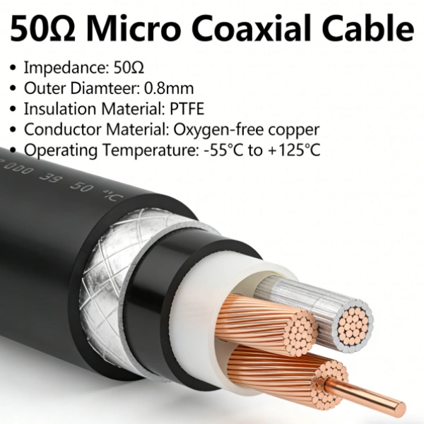
Construction:Center conductor (solid or stranded), dielectric (e.g., foam PE, PTFE), shield (foil + braid), and jacket.
Why it matters:Impedance mismatches cause signal reflections, degrading eye diagrams and increasing bit error rates .
2.2 Frequency Bandwidth and Attenuation
Frequency range:For 4K/8K, you may need performance up to several GHz per lane (e.g., 3–12 GHz depending on protocol and encoding).
Attenuation:Look at dB/m or dB/ft at your Nyquist frequency. Lower is better.
Example:A good 48 AWG micro coax might show < 1 dB loss at 3 GHz over short lengths, which is acceptable for many internal display links .
2.3 Shielding Effectiveness
Types:Aluminum foil + tinned copper braid is common, with braid coverage ≥ 85%.
Why it matters:High shielding effectiveness (> 90 dB) reduces crosstalk and EMI, which is critical in noisy environments like laptops with multiple high-speed interfaces .
2.4 Size, Flexibility, and Bend Radius
Typical diameters:0.2 mm to 0.8 mm for ultra-fine coax used in displays.
Bend radius:Should be small (e.g., 2–5× the cable diameter) for tight routing in hinges or moving parts.
Cycle life:Specify the number of flex cycles required (e.g., 10,000+ for a laptop hinge) .
2.5 Connector Compatibility
Pitch and pin count:Match the cable to the connector (e.g., 0.3 mm pitch, 30-pin connectors are common in high-res displays).
Impedance continuity:The connector must maintain the same impedance as the cable to avoid reflections .
5. Practical Implementation Tips and Common Pitfalls
5.1 Do’s
Specify impedance and toleranceclearly in your drawings.
Request insertion loss and phase balance datafrom suppliers.
Simulatecritical links with IBIS-AMI or channel simulation models if available.
Use consistent shieldingacross the entire signal path, including connectors and PCB traces.
5.2 Don’ts
Don’t assume all “48 AWG coax” is equal.Construction and materials vary significantly.
Don’t ignore return loss.Poor matching at connectors can ruin an otherwise good cable.
Don’t mix cable typesin a differential pair (e.g., one coax and one twisted pair).
Don’t forget about crosstalkin dense cable bundles; maintain spacing or use grounded guards.
6. Frequently Asked Questions
Q1: Can 48 AWG micro coax really handle 8K?
A: Yes, for short-reach internal links (e.g., < 300 mm) when the protocol data rate per lane is within the cable’s frequency capability. System-level testing is essential .
Q2: Is micro coax better than FPC for 4K displays?
A: For high-speed interfaces like eDP and MIPI DSI, micro coax generally offers better signal integrity due to controlled impedance and superior shielding .
Q3: How many flex cycles should I specify?
A: For laptop hinges, 10,000–20,000 cycles is a common minimum. For wearables or foldable devices, specify 100,000+ cycles with a qualified cable and strain-relief design .
Q4: Do I need expensive connectors?
A: You need connectors designed for high-speed differential signals that match your cable’s impedance. Many off-the-shelf connectors from vendors like I-PEX or Hirose are suitable .
7. Conclusion and Next Steps
The “best” micro coaxial cable for a 4K/8K display is the one that meets your specific electrical, mechanical, and cost requirements. Start by defining your data rate, length, and environmental needs. Then, shortlist cable constructions that match your impedance and frequency targets. Finally, validate your top choices with real hardware testing.
If you need help selecting a cable for your display project, prepare your interface type, resolution, cable length, and connector pitch, and share those details with a qualified cable assembly supplier to get tailored recommendations.
Advanced Driver-Assistance Systems (ADAS) are evolving rapidly, demanding higher resolution, lower latency, and greater reliability from in-vehicle camera systems. At the heart of this evolution lies the Serializer/Deserializer (SerDes) architecture, which converts parallel video data into high-speed serial streams. To transmit these multi-Gbps signals reliably across the vehicle, Micro Coaxial Cablehas become the industry-standard physical medium.
This guide provides a technical yet practical overview for B2B engineers and procurement specialists on selecting and implementing micro coax for next-gen ADAS camera modules.
Why Micro Coax is Essential for Automotive SerDes
Unlike standard coaxial or twisted-pair cables, micro coaxial cable offers a unique balance of electrical performance and mechanical flexibility in a miniature form factor (typically 0.3mm–1.0mm OD). Its importance in ADAS stems from three core advantages:
Superior Signal Integrity:The controlled 50Ω impedance and continuous shielding minimize signal reflection and attenuation, ensuring clean data transmission for high-resolution cameras (e.g., 8MP+).
EMI/EMC Performance:Vehicles are electrically noisy environments. The 360° dual shielding (foil + braid) effectively contains high-frequency radiation, helping systems pass stringent CISPR 25 automotive EMC tests.
Space & Weight Savings:Its tiny footprint allows routing through tight spaces (e.g., inside car doors for surround-view cameras or within mirror assemblies), reducing overall harness weight—a critical factor for EV range optimization.
Critical Technical Parameters for Selection
Selecting the wrong cable leads to bit errors, link instability, or EMC failures. Focus on these non-negotiable specifications:
1. Impedance and Tolerance
Standard:50Ω is mandatory for most automotive SerDes interfaces (GMSL, FPD-Link, MIPI A-PHY).
Tolerance:Demand ±2Ω or tighter. Variations cause signal reflections, closing the “eye diagram” and increasing Bit Error Rate (BER).
Data Point:Verify the cable’s insertion loss curve (dB/m @ frequency). A quality automotive micro coax typically supports frequencies up to 6–20 GHz.
Rule of Thumb:Calculate total channel loss (cable + connector + PCB trace) against your SerDes chipset budget. Exceeding this budget causes link drops.
3. Shield Effectiveness
Construction:Insist on dual shielding(Aluminum Mylar foil + Tinned Copper braid).
Coverage:Braid coverage should exceed 85–90%. Inadequate coverage creates “leaky cables” that fail EMC testing.
4. Environmental Rating
Temperature:Standard operating range must be –40 °C to +105 °C (engine bay applications may require +125 °C).
Durability:Look for certifications confirming resistance to oil, gasoline, and UV exposure.
Real-World ADAS Applications
Micro coaxial cable is not a generic wire; it solves specific problems in modern vehicle architectures:
Surround View Camera Systems:Connecting four or more wide-angle cameras to a central ECU, requiring consistent impedance across 3–5 meter runs.
Front-Facing Perception Cameras:Transmitting high-bandwidth data for AEB (Automatic Emergency Braking) and Lane Keeping Assist, where signal integrity is directly linked to safety.
E-Mirror (Camera Monitor Systems):Replacing traditional side mirrors with cameras, requiring thin, flexible cables that route through narrow pivot points without signal degradation.
Installation Pitfalls and Best Practices
Even the best cable fails if installed incorrectly. Avoid these common engineering mistakes:
Do’s:
Maintain Bend Radius:Never bend below the manufacturer’s specification (typically 10x the cable diameter for static bends). Kinking destroys the dielectric geometry and impedance.
Ensure 360° Grounding:The cable shield must make full, uninterrupted contact with the connector shell and chassis ground. Poor grounding is the #1 cause of EMI issues.
Use Proper Strain Relief:Secure cables with clips or ties, but avoid over-tightening, which deforms the jacket and alters electrical properties.
Don’ts:
Don’t Mix Components:Using a generic connector with a specific micro coax often results in impedance mismatches. Always use validated connector-cable assemblies.
Don’t Ignore Pair Skew:If your SerDes link uses a differential pair over two micro coaxes, keep them tightly twisted and matched in length to prevent timing skew.
B2B Buyer’s Checklist: Avoiding Costly Mistakes
When sourcing micro coaxial cable for ADAS projects, use this table to vet suppliers and avoid “specification washing”:
Parameter
Low-Quality Supplier (Avoid)
High-Quality Supplier (Choose)
Consequence of Ignoring
Impedance Tolerance
±5 Ω or untested
±2 Ω or tighter
Signal reflections, link instability
Shielding
Single foil shield
Foil + Braid (>85% coverage)
EMC test failure
Documentation
Basic datasheet
VNA/TDR Reports, IL Curves
Inability to validate performance
Connector System
Generic RF connectors
Automotive-locking connectors
Vibration-induced disconnection
Conclusion: Engineering Reliability into Every Meter
Micro coaxial cable is far more than just a wire; it is a precision RF component critical to the safety and functionality of next-generation ADAS cameras. For B2B stakeholders, success lies in treating the cable as part of a complete high-speed signal chain. By prioritizing impedance control, insertion loss characteristics, and robust shielding—while adhering to strict installation protocols—you ensure that high-speed SerDes links remain resilient in the harshest automotive environments. Specify wisely, demand data, and test rigorously to build ADAS systems that are not only advanced but fundamentally reliable.
When designing or sourcing micro coaxial cable assemblies for high-speed data, RF, or video applications, one question comes up again and again:
What impedance values are possible—and how tight can the tolerance be?
This guide answers that question directly. You will learn which impedance values are standard, what ranges are achievable, which factors influence the final number, and how to specify realistic requirements for your next project.
Standard Impedance Values for Micro Coaxial Cable Assemblies
Most micro coaxial cable assemblies are manufactured to a few well-established characteristic impedance points. These values dominate the market because they match common connectors, test equipment, and industry standards.
Most Common Impedance Values
50 Ω
The default choice for high-speed digital, RF, and microwave applications.
Standard for PCIe, USB, MIPI, LVDS, and many wireless modules.
Offers a good balance between power handling and signal loss.
75 Ω
The standard for broadcast video, consumer video links, and some measurement systems.
Optimized for minimum attenuation in video distribution.
100 Ω (Differential)
Common for high-speed differential pairs such as PCIe, USB SuperSpeed, and DisplayPort.
Achieved by pairing two matched 50 Ω single-ended lines.
While other values exist (for example, 85 Ω differential or legacy 93 Ω systems), 50 Ω, 75 Ω, and 100 Ω differential account for the vast majority of commercial micro coaxial assemblies.
Typical Available Impedance Ranges
So, what impedance values can you actually achieve? The answer depends on cable size, dielectric material, and manufacturing capability.
Typical Impedance Ranges by Cable Type
Standard Micro Coax (e.g., 1.13 mm, 1.32 mm OD)
50 Ω ± 2 Ωis the most common specification.
Tighter tolerance of ±1 Ωis achievable with controlled manufacturing and testing.
Smaller Micro Coax (e.g., 0.81 mm, 0.64 mm OD)
Primarily available in 50 Ωversions.
75 Ωversions are less common but possible for specific video applications.
Custom or Specialty Designs
Impedances from 42.5 Ω to 75 Ωcan be produced, but this is usually project-specific.
Outside the 50 Ω / 75 Ω mainstream, costs rise and lead times extend.
Achievable Tolerance Levels
Impedance tolerance is just as important as the target value. Typical tolerance levels are:
Standard Tolerance:± 2 Ω
Tight Tolerance:± 1 Ω
Ultra-Tight Tolerance (Special Process Control):± 0.5 Ω
Important:Tighter tolerances require more rigorous process control and 100% testing, which increases cost.
Key Factors That Determine Achievable Impedance
To understand what impedance values are possible, you need to know the levers that control it. The characteristic impedance of a coaxial structure is governed by a physical formula:
Z₀ ≈ (60 / √εᵣ) × ln(D/d)
Where:
Z₀= Characteristic impedance
εᵣ= Dielectric constant of the insulation material
d= Outer diameter of the inner conductor
D= Inner diameter of the outer conductor (shield)
This formula reveals the four primary control knobs:
1. Inner Conductor Diameter (d)
A larger inner conductor lowers impedance; a smaller one increases it.
2. Outer Conductor Diameter (D)
A larger shield diameter increases impedance; a smaller one decreases it.
3. Dielectric Constant (εᵣ)
Solid PE≈ 2.3
Foam PE≈ 1.5 – 1.6
PTFE / FEP≈ 2.0 – 2.1
A lower dielectric constant allows for higher impedance with the same physical dimensions.
4. Structural Uniformity
Impedance is only useful if it is consistent. Variations in:
Conductor eccentricity
Dielectric thickness
Shield concentricity
…will cause impedance ripple, which leads to reflections and degraded signal integrity.
Impedance Options by Application
Choosing the right impedance is not just about what is possible, but what makes sense for your application.
Recommended Impedance Values by Application
High-Speed Digital (PCIe, USB, MIPI, LVDS)
Single-ended:50 Ω
Differential:100 Ω
RF & Microwave (Antennas, GPS, 5G Modules)
Industry standard is 50 Ωto match instruments and connectors.
Video (HDMI, SDI, Analog Video Links)
Professional and broadcast: 75 Ω
Some compact camera links: 50 Ω or 100 Ω differentialmay be used.
Automotive (ADAS, Cameras, Radar)
Camera and display links: 50 Ω or 100 Ω differential
Radar modules: 50 Ω
How to Specify Impedance for Your Micro Coax Assembly
If you are an engineer, buyer, or project manager, here is a practical checklist to define your impedance requirements clearly:
1. State the Target Impedance
Be explicit: e.g., “50 Ω single-ended” or “100 Ω differential”.
TDR (Time Domain Reflectometry):Industry standard for measuring characteristic impedance.
Frequency:Specify the TDR rise time (e.g., 35 ps) for fair comparison between suppliers.
4. Control the Full Signal Path
Impedance is a system property. Ensure connectors, PCB footprints, and termination schemes are designed for the same impedance.
5. Discuss Trade-offs with Your Supplier
If you need a non-standard value (e.g., 60 Ω or 85 Ω differential), talk to your cable manufacturer early. They can help you understand feasibility, tooling costs, and lead time.
Conclusion
In summary, most micro coaxial cable assemblies are available at standard impedances of 50 Ω, 75 Ω, and 100 Ω differential, with ±2 Ωbeing the common tolerance and tighter ±1 Ω or ±0.5 Ωoptions possible for high-performance applications. The achievable impedance is determined by the physical design of the cable—conductor sizes and dielectric constant—as well as the manufacturer’s process control and testing capabilities.
For B2B buyers and engineers, the key is to specify a realistic impedance target, a practical tolerance, and a clear test method, while treating impedance as one part of a complete, matched signal chain.
In today’s high-density, high-frequency electronic designs, selecting the right interconnect solution is crucial. When space is tight and signal integrity matters, engineers increasingly turn to Micro Coaxial Cable. At FRS, we specialize in manufacturing and supplying high-quality 50Ω micro coaxial cables designed for satellite, RF, and antenna applications. With a minimum order quantity (MOQ) as low as 50 pieces, optional high-temperature ratings, and fast global shipping, our cables offer both performance and flexibility for prototyping and volume production.
What Is a Micro Coaxial Cable?
A Micro Coaxial Cable, often called Micro Coax, is a miniature coaxial cable featuring a very small outer diameter—typically between 0.3 mm and 1.2 mm. Despite its size, it retains the classic coaxial structure: a central conductor, dielectric insulator, metallic shield, and outer jacket. This compact design allows it to carry high-frequency signals with excellent impedance control and shielding effectiveness, making it ideal for space-constrained applications.
Typical Applications
Satellite communications: Signal routing between antennas, transceivers, and onboard electronics.
RF and wireless systems: Connections for antennas, filters, amplifiers, and test equipment.
High-density electronics: Smartphones, wearables, laptops, and other portable devices.
Medical devices: Ultrasound probes, endoscopes, and diagnostic equipment.
Automotive and aerospace: In-cabin electronics, sensors, and control systems.
Why 50Ω Is the Standard for RF and Satellite Systems
In the world of RF and microwave engineering, 50Ω impedanceis the de facto standard. This value represents a practical compromise between two key factors:
Maximum power handling: Higher impedance (e.g., 75Ω) reduces voltage stress but increases current.
Low signal loss: Lower impedance reduces conductor loss but increases dielectric loss.
The 50Ω standard provides a balanced solution, minimizing signal reflections (low VSWR) and ensuring reliable power transfer. For satellite and RF applications, using a true 50Ω cable is critical to avoid standing waves that can cause signal distortion, reduced efficiency, and potential damage to sensitive components.
FRS High-Quality 50Ω Micro Coaxial Cable
At FRS, we manufacture micro coaxial cables built for demanding applications. Our standard 50Ω cables are engineered for consistent electrical performance, mechanical durability, and long-term reliability.
Key Electrical Specifications
Impedance: 50Ω ± 2Ω (typical), ensuring compatibility with standard RF equipment.
Frequency Range: Up to 6 GHz for standard grades; higher-frequency options available for specialized needs.
Velocity of Propagation: ~70–80%, depending on dielectric material.
Shielding Effectiveness: >90 dB, providing excellent immunity to EMI and RFI.
Mechanical and Environmental Specs
Outer Diameter: 0.3 mm to 1.0 mm, depending on AWG size.
Conductor: High-purity stranded or solid copper, with optional silver plating for better高频 performance.
Dielectric: Low-loss options like PFA, FEP, or PE.
Shielding: Multiple layers of braided copper or spiral-wound foil for high coverage.
Jacket: Standard PVC or LSZH, with high-temp options using PFA/FEP for -50°C to +200°C operation.
Micro Coax for Satellite, RF, and Antenna Applications
Satellite Communication Links
Signal Integrity: Stable 50Ω impedance and low VSWR preserve signal quality over long distances.
Phase Stability: Low dielectric loss and stable materials ensure consistent phase characteristics, critical for phased-array antennas and high-speed data links.
Lightweight Design: Thin, lightweight cables reduce overall system mass, a key advantage in aerospace applications.
RF Test and Measurement
Repeatable Measurements: Consistent impedance and low loss ensure accurate, repeatable results.
Durability: Flexible yet robust construction withstands repeated bending in lab and field environments.
Connector Compatibility: Easily terminated with SMA, SMB, MCX, U.FL, and other standard RF connectors.
Antenna and Wireless Systems
Compact Routing: Small diameter and flexibility simplify installation in tight spaces.
Broadband Performance: Low attenuation and stable impedance across a wide frequency range support multi-band and wideband applications.
EMI Protection: High shielding effectiveness prevents signal leakage and ingress, ensuring reliable communication.
High-Temperature Micro Coax Options for Harsh Environments
Standard micro coax cables typically operate within -20°C to +80°C. For more demanding environments, FRS offers high-temperature variants designed for continuous operation up to +200°C.
Material Choices for High-Temperature Performance
Dielectric & Jacket: PFA and FEP fluoropolymers offer excellent thermal stability, chemical resistance, and low dielectric loss.
Conductors: Silver-plated copper alloys maintain high conductivity and resist oxidation at elevated temperatures.
Connectors & Terminations: Assemblies use high-temp rated connectors and special soldering processes to ensure reliability.
Application Scenarios
Automotive: Under-hood and engine bay applications.
Industrial: Near motors, inverters, and heating elements.
Aerospace & Defense: Avionics, radar, and satellite systems.
Process Control: Sensors and instrumentation in high-temperature industrial processes.
Low MOQ and Flexible Procurement: Start with 50 Pieces
Recognizing that project needs vary, FRS offers a competitive minimum order quantity (MOQ) of just 50 pieces. This low barrier to entry provides significant advantages:
Prototyping and R&D: Test and validate designs without a large upfront investment.
Low-Volume Production: Ideal for niche products, pilot runs, and custom equipment.
Reduced Inventory Risk: Order smaller batches to match production schedules and avoid excess stock.
Fast Shipping and Global Logistics
Time-to-market is critical. FRS is committed to fast, reliable delivery:
Standard Lead Time: 1-2 weeks for most standard cables and assemblies.
Expedited Options: Rush production and shipping available for urgent projects.
Global Shipping: We partner with trusted carriers (DHL, FedEx, UPS) to serve customers worldwide.
Local Support: Regional warehouses and partners in key markets help reduce shipping times and costs.
Customization and Technical Support
Every application is unique. FRS provides extensive customization options and expert support:
Custom Geometries: We can tailor conductor size, dielectric, shielding, and jacket to meet specific electrical and mechanical requirements.
Connector Assembly: Our engineers can recommend and terminate cables with a wide range of RF and board-to-board connectors.
Technical Consultation: From initial design to final testing, our team helps you select the optimal cable for your application.
Quality Assurance: We offer 100% electrical testing, including continuity, insulation resistance, and hi-pot testing, with full documentation available.
Why Choose FRS for Your Micro Coaxial Cable Needs?
Quality: We use premium materials and adhere to strict manufacturing standards (UL, RoHS, REACH).
Performance: Our cables deliver reliable 50Ω impedance and low loss for critical RF and satellite links.
Flexibility: Low MOQ of 50 pieces, plus custom options for both prototyping and volume production.
Durability: High-temperature variants available for operation up to +200°C.
Speed: Fast lead times and global shipping to keep your projects on schedule.
Expertise: Decades of combined experience in micro coax design and manufacturing.
Frequently Asked Questions (FAQ)
Q1: What is the typical lead time for an order of 50 pieces?
A: Standard lead time is 1-2 weeks. Rush services are available for urgent needs.
Q2: Can I get a high-temperature version of a standard 50Ω micro coax?
A: Yes, we offer high-temp variants with PFA/FEP materials rated for continuous operation up to +200°C.
Q3: Do you provide cables with connectors attached?
A: Yes, we offer fully assembled cables with a wide variety of RF and board-to-board connectors.
Q4: Is 50Ω impedance critical for my application?
A: For satellite, RF, and most wireless systems, using a true 50Ω cable is essential for minimizing signal reflections and ensuring reliable performance.
Q5: What payment and shipping options do you support?
A: We accept T/T and major international payment methods. We ship globally via express couriers like DHL, FedEx, and UPS.
Ready to Order or Need a Quotation?
Whether you need a small batch for prototyping or a large production run, FRS is ready to supply high-quality 50Ω micro coaxial cables at competitive wholesale prices. Contact our sales team today with your specifications for a fast, no-obligation quote.
In high-resolution camera modules, displays, and embedded vision systems, the MIPI (Mobile Industry Processor Interface) has become the de facto standard for camera (CSI-2) and display (DSI) interconnects. As resolutions, frame rates, and channel counts increase, the humble micro coaxial cablehas evolved from a simple wiring component into a critical high-speed interconnect that determines image quality, system stability, and EMI compliance.
This article provides an in-depth look at the role of the 90Ω micro coaxial cablein MIPI applications, its electrical and mechanical characteristics, and practical guidelines for selection and design.
Why 90Ω for MIPI?
MIPI D-PHY and C-PHY specifications define the differential impedance of the transmission line, not a single-ended value. The differential impedance of a 90Ω micro coaxial cable is the correct target for a 100Ω differential MIPI pair.
Differential Impedance: The impedance measured between the two conductors of a differential pair.
Single-Ended Impedance: The impedance from one conductor to ground.
For a well-designed differential pair, the relationship is approximately:
Thus, a 100Ω differential target is achieved with a 50Ω single-ended impedance. A 90Ω differential cable is effectively a 45Ω single-ended cable, which is a standard and manufacturable value.
Industry Practice: Many MIPI cable and connector vendors specify their products as “90Ω differential” or “100Ω differential” to match the D-PHY standard. The slight difference between 90Ω and 100Ω is often within the tolerance of the overall channel, especially when considering PCB traces and connector transitions. The key is ensuring the entire channel is impedance-controlled and consistent.
MIPI Speeds and the Need for Micro Coax
MIPI specifications define the following per-lane data rates:
D-PHY: 1.5 Gbps per lane in HS mode (with multi-lane aggregation up to several Gbps total).
C-PHY: Up to 6 Gbps per lane (using a 3-phase encoding scheme).
At these multi-gigabit speeds, even small impedance mismatches, dielectric loss, or crosstalk can cause reflections and degrade the eye diagram, leading to image artifacts like sparkles, flickering, or frame drops.
Why Micro Coax is Essential:
Precise Impedance Control: The coaxial structure (center conductor, dielectric, shield, jacket) allows for tight control over single-ended impedance (typically 45–50Ω), ensuring the differential impedance is close to the 90–100Ω target.
Superior Shielding: Each micro coax pair is individually shielded, drastically reducing crosstalk between adjacent MIPI lanes and protecting against external EMI/RFI.
Controlled Loss: High-frequency dielectric materials (like FEP or PTFE) minimize insertion loss, which is critical for maintaining signal integrity over longer cable lengths.
Mechanical Flexibility: With outer diameters as small as 0.3–0.5 mm, micro coax can be routed through tight spaces and bent without significant performance degradation, unlike stiff FPC/ribbon cables.
Anatomy of a 90Ω Micro Coaxial Cable
A typical 90Ω micro coaxial cable consists of four main layers:
Center Conductor: Usually silver-plated copper (SPC) or bare copper. A larger diameter lowers resistance but increases capacitance, so a balance is needed for the target impedance.
Dielectric Insulation: This layer defines the single-ended impedance. Materials like foamed PTFE or FEP are common for their low dielectric constant (Dk) and low loss. The dielectric thickness is tightly controlled.
Shielding Layer: Typically a combination of a thin aluminum foil and a tinned copper braid. This dual-layer shield provides >90% coverage for excellent EMI protection and low radiation.
Outer Jacket: A flexible material like PVC or polyurethane that protects the cable from mechanical stress and environmental factors. The choice of jacket affects flexibility, temperature range, and flame retardancy.
Matching the 90Ω Micro Coax to MIPI Connectors
The performance of the entire MIPI channel is only as good as its weakest link. The transition from PCB trace to connector to cable must be seamless.
Connector Impedance: Choose connectors explicitly specified for 90Ω or 100Ω differential impedance. Popular MIPI micro-coax connectors include I-PEX (e.g., CABLINE® series), Hirose, JAE, and others. Mismatched connectors can cause significant reflections.
Connector Geometry: The pad size, via stub, and routing on the PCB must be designed to match the connector’s impedance profile. Poor matching at the connector interface is a common cause of signal integrity issues.
Cable-to-Connector Termination: The shield must be securely grounded to the connector’s backshell, and the center conductor must be precisely crimped or soldered. Inconsistent termination can create impedance discontinuities and skew between channels.
Channel Length, Loss Budget, and Practical Limits
The maximum reliable length of a 90Ω micro coaxial cable for MIPI depends on several factors:
Data Rate per Lane: Higher speeds (e.g., 4–6 Gbps) have less tolerance for loss.
Number of Lanes: More lanes increase overall channel loss and crosstalk.
Cable Construction: Materials and shielding quality directly impact loss and EMI performance.
General Guidelines:
For 1.5 Gbps D-PHY, a well-designed micro-coax cable can often reach 150 mmwithout significant signal degradation.
For 2.5–4 Gbps, lengths are typically limited to 50–100 mm.
Some specialized systems, like certain embedded vision platforms, use high-quality micro-coax to achieve up to 1 meterfor 4-lane MIPI, but this requires careful design and often involves trade-offs.
Loss Budget Analysis: Engineers should perform a channel loss budget that accounts for the PCB trace, connector, and cable losses. If the loss at the target frequency is too high, options include:
Shortening the cable.
Reducing the data rate or number of lanes.
Using a lower-loss cable construction.
Adding active components like a repeater or retimer.
Micro Coax vs. FPC/Ribbon Cables for MIPI
While FPC/ribbon cables are cheaper and easier to mass-produce, they fall short for high-performance MIPI applications.
Feature
90Ω Micro Coaxial Cable
FPC / Ribbon Cable
Impedance Control
Excellent and consistent due to coaxial structure.
Difficult to control precisely over long lengths and multiple layers.
EMI/Crosstalk
Excellent, with individual shielding for each pair.
Poor, with significant crosstalk between adjacent conductors.
Bandwidth
Supports multi-gigabit per lane speeds reliably.
Performance degrades rapidly at high frequencies.
Flexibility
Good for tight-radius bends in 3D spaces.
Can fatigue or crack if bent repeatedly in tight radii.
Best For
High-resolution cameras, long MIPI runs, noisy environments.
Very short connections on rigid PCBs where cost is critical.
🛠️ Design and Manufacturing Considerations
PCB Layout: Maintain symmetry in differential pairs and minimize stubs. Ensure the impedance of the PCB traces matches the cable and connector (typically 45–50Ω single-ended).
Grounding: Use a solid ground plane near the high-speed signals. Connect the shields of all micro-coax cables to a common ground point on the PCB to avoid ground loops.
Channel-to-Channel Matching: For multi-lane MIPI, ensure the electrical length of each lane is matched to within a few millimeters to prevent skew, which can cause color misalignment or image tearing.
Manufacturing Quality: The quality of the cable assembly process is paramount. Variations in shielding termination, crimping, and soldering can ruin the impedance match. Work with vendors who have proven experience in high-speed MIPI cable assemblies.
Applications of 90Ω Micro Coax in MIPI Systems
Mobile Devices: Smartphones, tablets, and AR/VR headsets use micro-coax to connect high-resolution cameras and displays to application processors in ultra-compact spaces.
Automotive: In-vehicle cameras for ADAS and surround-view systems rely on shielded micro-coax to maintain signal integrity in harsh electrical environments.
Industrial & Embedded Vision: Machine vision cameras and inspection systems use micro-coax to carry MIPI signals between sensors and processing units, often in robotic or moving assemblies.
Edge AI & SBCs: Platforms like the NVIDIA Jetson Orin use micro-coax to connect multiple MIPI cameras, where signal integrity is critical for AI inference.
Key Takeaways for Your MIPI Design
When specifying a 90Ω micro coaxial cablefor your MIPI interface, focus on the entire channel, not just the cable itself. Ensure that the PCB, connectors, terminations, and cable are all designed and specified as a system to meet your performance targets for data rate, length, and EMI.
The coaxial cable, with its concentric conductor-dielectric-shield-jacket structure, has been a cornerstone for RF, video, and broadband transmission for decades. As we enter 2026, the industry is undergoing a significant shift. While traditional coax remains vital for infrastructure, a new class of interconnect—micro coaxial cable—is redefining what’s possible inside high-density, high-frequency devices.
This article provides a detailed, engineering-focused comparison to help you select the right cable for your 2026 project.
What is a Micro Coaxial Cable?
A micro coaxial cable is a miniaturized version of a standard coax, retaining the same four-layer structure but engineered for extreme space constraints and high-frequency integrity.
Size & Structure: With outer diameters (OD) as small as 0.2 mm to 1.16 mm, they use ultra-fine center conductors (down to 52 AWG), precision dielectric layers, and multi-layer shields (braid + foil).
Performance: Despite their size, they are designed for GHz-rangefrequencies with tight impedance control (typically 50 Ω), excellent shielding, and low loss, making them ideal as “precision transmission lines” for internal device connections.
Side-by-Side Comparison
Dimension
Micro Coaxial Cable
Traditional Coaxial Cable
Physical Size & Density
OD:0.2–1.16 mm. Enables ultra-high-density harnesses in compact devices like smartphones and drones.
OD:Several mm to over 1 cm (e.g., RG-6 is ~6.9 mm). Prioritizes robustness over density.
Electrical Performance
Maintains stable 50 Ω / 75 Ωimpedance and low loss at GHz frequenciesover short distances.
Optimized for low-loss, long-distancetransmission (100s of meters) at MHz to low GHzfrequencies.
Signal Integrity
Excellent EMI shielding and impedance consistency are critical for multi-gigabit differential signals (e.g., MIPI, HDMI).
Susceptible to crosstalk and interference over long runs without careful installation. Shielding is robust but less critical for its primary long-haul role.
Mechanical & Environmental
Designed for high flexibility and tight bend radii. Built to withstand millions of flex cycles in hinges and connectors.
Built for tensile strength and crush resistance. Less flexible, with bend radius limited to several times the cable diameter.
Manufacturing & Cost
High-precision, high-costprocess. Yields are sensitive to tiny dimensional variations.
Mature, high-volume, lower-costmanufacturing. Easier to automate and scale.
Applications
Internal device interconnects: smartphones, wearables, medical scopes, automotive radar, and high-res displays.
Infrastructure: cable TV (CATV), broadband, CCTV, 5G base stations, and long-haul RF links.
Application-Driven Selection
When to Choose Micro Coaxial Cable
High-Speed Digital Video: For MIPI CSI-2 camera links or eDP/DisplayPort internal connections, micro coax ensures signal integrity with minimal skew and EMI.
Medical & Industrial Imaging: In endoscopes or industrial cameras, it provides high SNR and immunity to EMI in compact, dynamic environments.
Automotive & 5G: For ADAS radar and 5G mmWave modules, it offers a controlled-impedance RF path that handles vibration and tight spaces.
Wearable & Foldable Electronics: Its flexibility and small bend radius are essential for devices like smartwatches and foldable phones.
When to Choose Traditional Coaxial Cable
Long-Distance Infrastructure: For distributing cable TV (CATV) or broadband over hundreds of meters, its low attenuation is paramount.
RF Distribution: As a building block for antenna feeders and base station jumpers where distance and weather resistance are key.
Harsh Outdoor Environments: For direct-buried or tower-mounted runs, its mechanical robustness and weatherproofing are critical.
Engineering Trade-Offs
1. Attenuation vs. Length
Micro Coax: Attenuation is dominated by conductor and dielectric losses. It’s excellent for short links (cm to a few meters)but losses become prohibitive at longer lengths, especially beyond 10-20 meters in the GHz range.
Traditional Coax: Designed for low loss over long distances. High-quality cables can achieve losses under 0.1 dB/m at 1 GHz, making them suitable for 100+ meter runs.
2. Shielding vs. Flexibility
Micro Coax: Achieves high shielding effectiveness (60-100 dB) with ultra-thin layers. The design is a constant trade-off between shielding, flexibility, and insertion loss.
Traditional Coax: Features robust, thick shields (braid + foil) that are highly effective but limit flexibility. Semi-rigid variants offer superior performance at the cost of being non-flexible.
3. Impedance Control
Micro Coax: Requires extremely tight dimensional tolerances to maintain a stable 50 Ω or 75 Ω impedance, which is non-negotiable for multi-gigabit signals.
Traditional Coax: Also specifies impedance, but minor variations are often acceptable for its typical applications, where small mismatches cause less harm over long distances.
Hybrid Architectures for 2026
Modern systems often use a hybrid approach:
Inside the Box: Micro coaxhandles high-speed, high-density internal links.
Outside the Box: Traditional coaxor fibermanages long-distance distribution.
This leverages the strengths of each technology, creating a cost-effective and high-performance system.
Practical Selection Guide
Define the Environment: Is it a short, high-density internal link(favors micro coax) or a long outdoor run(favors traditional coax)?
Match the Frequency & Data Rate: Higher frequencies and data rates demand the superior performance of micro coax for short links.
Evaluate Mechanical Stress: Constant flexing or tight bends point to micro coax. Stationary, protected runs can use traditional coax.
Consider the Ecosystem: Factor in connector availability, manufacturing capabilities, and total cost, not just the raw cable price.
The Future: Miniaturization & Performance
By 2026, micro coaxial cable is no longer a niche product. Driven by 5G, autonomous vehicles, and AR/VR, the industry is pushing towards even smaller diameters (e.g., 52 AWG), advanced shielding, and lower-loss dielectrics. As devices become more powerful and compact, the ability to move clean, high-speed signals through minimal space will only increase the importance of micro coax.
Choosing between micro and traditional coax is not about one being “better”; it’s about selecting the right tool for the job. Understanding their distinct strengths ensures your 2026 designs are not just functional, but optimized for performance, reliability, and cost.
As a professional Micro Coaxial Cable Manufacturer, we provide high-performance micro coaxial cable and cable assembly solutions. We offer comprehensive OEM/ODM services, supporting custom diameters, shielding structures, impedance, and connector types to meet the stringent requirements of industries like medical, automotive, and consumer electronics.
🔬 Engineering Micro Coaxial Cables: 0.22–1.16 mm
Our micro coaxial cables are engineered to excel in compact, high-frequency applications.
Ultra-Fine Diameter: With an outer diameter range of 0.22–1.16 mm, these cables are significantly thi.
Micro-coaxial cables are the unsung heroes of our connected world. Packed into everything from cutting-edge smartphones and laptops to life-saving medical devices and high-frequency aerospace systems, they carry vital signals that power modern technology. As devices shrink and demand for higher data rates increases, a critical challenge emerges: how do we make the insulation around these tiny center conductors perform better? This is where nanotechnology steps in, revolutionizing micro-coaxial insulation for unparalleled performance.
Why Insulation Matters (Especially for Micro-Coax)
The insulat.
The recent publication of the Coaxial Cable Market Research Report marks a critical resource for industry stakeholders—from manufacturers and suppliers to procurement managers and technology investors. As a foundational component in signal transmission, coaxial cables (often shortened to “coax cables”) remain indispensable across sectors like telecommunications, media, industrial automation, and aerospace. This report not only quantifies the current market size but also maps future trajectories, shedding light on how technological advancements and global demand shifts are reshaping the indus.
As 5G New Radio (NR) networks push into FR2 bands—spanning 24.25 GHz to 40 GHz and beyond—the performance of every interconnect in the RF front-end is under unprecedented scrutiny. Among these, the micro coaxial cable termination solutionis a critical yet often underestimated factor. In high-frequency systems, even minor impedance mismatches can lead to significant signal reflection, degrading modulation accuracy and overall link budget.
This article introduces a new termination approach engineered to achieve ultra-low VSWRfor 5G mmWave modules, addressing the signal integrity, manufacturability, a.
The evolution from traditional power grids to intelligent Smart Grid Systems demands a robust, reliable, and high-performance communication infrastructure. At the heart of this critical communication layer lies a proven and essential technology: Coaxial Cable. While often associated with video transmission, coaxial cable’s unique properties make it an indispensable component for enabling numerous Smart Grid functionalities where high-frequency data signals and resilience are paramount.
The Smart Grid Communication Imperative
Smart Grid Systems integrate digital communication techn.
In the demanding arenas of defense, aerospace, and industrial applications, reliability isn’t optional – it’s mission-critical. Equipment deployed on battlefields, aboard aircraft, within satellites, or on rugged factory floors must perform flawlessly under punishing conditions. When it comes to transmitting vital signals and power, Military-Grade Micro-Coaxial Cables represent the pinnacle of resilience, explicitly designed to withstand extreme environments where standard cables would rapidly fail. This article explores why these specialized cables are the indispensable backb.
KEL’s Micro Coaxial Cable solutions are at the forefront of modern electronic connectivity, offering exceptional performance in high-speed data transmission, miniaturization, and reliability. These connectors are integral to various.
OverviewMicro-Coax for HD Video is a cutting-edge coaxial cable engineered to deliver uncompromised high-definition video quality across professional and industrial applications. Designed for reliability, precision, and versatility,.
Contact Us Micro Coaxial Cable factory-(FRS).
Feel free to reach out to us for any inquiries or orders