How Propagation Delay Varies Across Different Micro Coaxial Cable Dielectrics
Ever wonder why signal timing is critical in high-speed electronics like 5G phones, radar systems, or advanced medical imaging? A key player hiding within your micro coaxial cables is propagation delay – the time it takes for an electrical signal to travel from one end of the cable to the other. Surprisingly, the tiny insulating material inside the cable, called the dielectric, has a massive impact on this delay. Let’s break down how different dielectric materials affect signal speed.
Propagation Delay 101: It’s About Speed
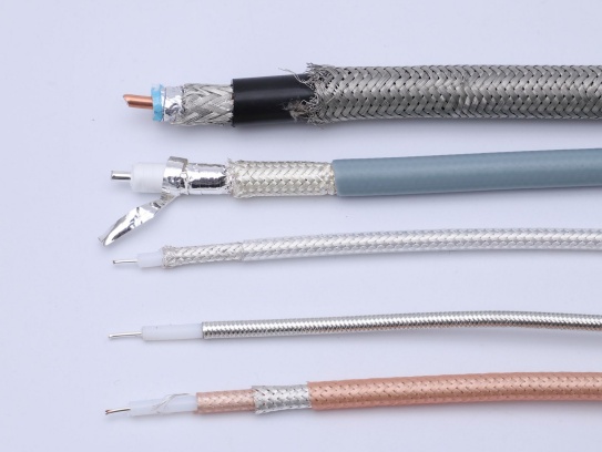
Imagine sending a runner through different types of terrain. Pavement = fast. Sand = slow. Electrical signals behave similarly within a cable. The conductor (the center wire) is the path, but the dielectric surrounding it is the “terrain.” Propagation delay (often measured in picoseconds per inch, ps/in, or nanoseconds per meter, ns/m) directly depends on how fast the signal travels along that path – its signal velocity.
The Critical Factor: Velocity of Propagation (VP%) and Relative Permittivity (Dk)
The speed of the signal inside the cable is always slower than the speed of light in a vacuum (c = ~3×10^8 m/s). We express this relative speed as a percentage:
- Velocity of Propagation (VP%) = (Actual Signal Speed / Speed of Light in Vacuum) x 100%
What determines this VP%? Primarily, the Relative Permittivity (Dk), or dielectric constant, of the insulating material. Dk measures how much the dielectric material “holds onto” or impedes the electromagnetic field created by the signal traveling along the conductor. A higher Dk means the signal travels slower, increasing propagation delay.
Dielectric Showdown: How Different Materials Stack Up
Here’s how common micro coaxial dielectrics compare regarding Dk, VP%, and their impact on propagation delay:
- Solid Polyethylene (PE):
- Dk: ~2.3
- VP%: ~66%
- Delay (approx): ~1.54 ns/m (51 ps/in)
- Impact: Most common. Offers a good balance of cost and performance for many applications. Delay is moderate but significant for very high speeds or long runs.
- Foamed Polyethylene (Foamed PE):
- Dk: ~1.5 – 1.8 (depends on the amount of foaming/air)
- VP%: ~75% – 82%
- Delay (approx): ~1.36 – 1.22 ns/m (45 – 40 ps/in)
- Impact: By incorporating tiny air bubbles (air has Dk=1), the average Dk of the dielectric is reduced. This lowers propagation delay significantly compared to solid PE – often by ~15-25%. Preferred where higher speed and lower loss are needed without going to more expensive options.
- Solid Polytetrafluoroethylene (PTFE / Teflon™):
- Dk: ~2.1
- VP%: ~69%
- Delay (approx): ~1.45 ns/m (48 ps/in)
- Impact: Slightly lower Dk and slightly higher VP% than solid PE. Offers excellent high-frequency stability and lower attenuation, but comes at a higher cost. Propagation delay is lower than PE but higher than Foamed PE.
- Expanded PTFE / Air-Space PTFE:
- Dk: ~1.4 – 1.6
- VP%: ~84% – 90%
- Delay (approx): ~1.19 – 1.11 ns/m (39 – 37 ps/in)
- Impact: The king of low loss and low delay in common micro coax. Creates microscopic air pockets within the PTFE matrix, drastically lowering the effective Dk. This results in the lowest propagation delay among standard options – potentially 25%+ faster than solid PE. Essential for extreme high-frequency (mmWave) and lowest-timing-jitter applications.
Real-World Consequences: Why Does Delay Matter?
- Timing Skew: In systems with multiple parallel data lines (like differential pairs or buses), different path lengths or cables with different dielectrics (hence different propagation delays) cause signals to arrive at their destination at slightly different times. This “skew” can corrupt data, especially at high speeds.
- Clock Distribution: Precise clock signals routed through cables with high propagation delay (or varying delays) can lead to timing errors in digital circuits.
- Phased Arrays & Beamforming: Radar and 5G antennas use multiple antenna elements. Consistent propagation delay from the source to each antenna element is critical to ensure signals combine coherently to form the correct beam pattern. Variations in delay degrade performance.
- High-Speed Digital Links: Meeting stringent setup/hold timing budgets in interfaces like PCIe, USB4, or HDMI requires predictable and minimal propagation delay through interconnects, including coaxial jumpers.
Key Takeaways for Micro Coax Selection:
- Lower Dk = Lower Propagation Delay = Faster Signals: Choose dielectrics with inherently low Dk (like PTFE) or engineered for low effective Dk (like Foamed or Expanded materials).
- Air is Your Friend (in the dielectric): Dielectrics incorporating air bubbles (Foamed PE, Expanded PTFE) consistently deliver the lowest propagation delay due to air’s near-perfect Dk of 1.0.
- Balance Needs: While low delay is critical for high-speed timing, also consider attenuation (signal loss), frequency bandwidth, bendability, temperature stability, and cost. Foamed PE often hits the sweet spot for performance/value in many applications. Expanded PTFE is the premium choice for the most demanding cases.
- Consistency Matters: For critical timing paths, ensure consistent dielectric type and construction across all relevant cables to minimize skew.
- Consult Datasheets: Always refer to the specific manufacturer’s datasheet for the exact cable type you are using. Actual VP% and Delay values can vary slightly based on exact construction and formulation.
The Bottom Line:
The seemingly insignificant insulator inside your micro coaxial cable has a profound effect on how fast your signals travel. By understanding that foamed and expanded dielectric structures offer the lowest propagation delay due to their reduced effective permittivity, you can make informed choices to optimize signal timing in your next high-frequency or high-speed digital design. Choosing the right dielectric is crucial for meeting critical timing requirements and ensuring system reliability.