Micro Coaxial Cable factory-(FRS)

1.13mm micro coaxial cable - Micro Coaxial Cable factory-(FRS)

Micro Coaxial Cable-Micro Coaxial Cable factory-(FRS)-FRS

Micro coaxial cable Tag: 1.13mm micro coaxial cable

How to Measure the Impedance of a Micro Coaxial Cable

Measuring the impedance of a micro coaxial cable is essential for ensuring signal integrity in high-frequency applications like medical devices, aerospace systems, smartphones, and compact RF modules. Unlike larger coax, micro coax (like 0.81mm, 1.13mm, or 1.37mm diameter cables) presents unique challenges due to its tiny size. Here’s a reliable, step-by-step method using professional equipment:

Why Micro Coax is Different:

  • Extremely Small Conductors: Direct probe contact or clamping can easily deform the fragile center conductor and thin dielectric, invalidating the measurement.
  • Shield Vulnerability: Even gentle pressure can displace the braid or foil shield, altering its impedance characteristics.
  • Fixtures are Critical: Specialized test fixtures or connectors are almost always mandatory.

Equipment You’ll Need:

  1. Vector Network Analyzer (VNA): Essential for measuring complex impedance (magnitude and phase).
  2. Calibration Standards (Cal Kit): Precisely matched to the connectors you’ll use (e.g., SMA, 2.92mm, 1.85mm). Calibrate the VNA at the fixture planes.
  3. Test Fixtures (Crucial for Micro Coax):
    • Jig/Launch Fixtures: Designed with precision grooves or clamps to hold the micro coax perfectly aligned without crushing it. Examples include GGB’s Picoprobe Model 40A/67A series or custom jigs.
    • Micro-Coaxial Connectors: Cable assemblies terminated with precision micro-coaxial connectors compatible with your VNA ports.
    • RF Probes (e.g., Wafer Probes): Ground-Signal-Ground (GSG) or Ground-Signal (GS) probes with tip pitches matching the cable’s scale. Require extremely careful handling and specialized probe stations.
  4. Connectorization: Professionally soldering or crimping precision micro-coax connectors to the cable ends, providing stable VNA interfaces.
  5. Cable Preparation Tool: Sharp coax stripper specific to the exact cable size for clean, length-controlled access to center conductor and shield without nicking.

Step-by-Step Measurement Process:

  1. Prepare the Sample: Cut a clean length of micro coax. If using connectors, have them professionally installed per manufacturer specs. If using a jig/probe station, carefully prepare the cable ends: strip the jacket precisely to expose a controlled length of the shield, then carefully strip the dielectric to expose a controlled length of the center conductor, ensuring no deformation.
  2. Connect/Install in Fixture:
    • ​**(Connectors):** Connect directly to VNA Ports 1 and 2.
    • ​**(Jig):** Secure the prepared cable ends into the jig’s grooves or clamps following instructions. Crucial: Apply minimal pressure – just enough to ensure good electrical contact without deforming the cable structure.
    • ​**(Probes):** Carefully lower the probes onto the prepared center conductor and shield points on each end. Use microscope alignment. Apply minimum pressure for contact.
  3. VNA Calibration: Perform a full 2-port calibration (SOLT – Short, Open, Load, Thru) at the point of contact. This removes errors from VNA, cables (if any), and test fixture up to the cable interfaces.
    • For jigs/probes: Calibrate using standards mounted within the jig/probe station itself if possible, or directly at the probe tips.
    • For connectors: Calibrate at the connector end-face.
  4. Measure S-Parameters:
    • Set the VNA frequency range appropriate for your application (e.g., DC to 20+ GHz for many micro coax).
    • Ensure the VNA sweep covers the relevant frequencies for your application.
    • Measure the full 2-port S-parameters (S11, S21, S12, S22).
  5. Convert to Impedance (Z): Use the VNA’s built-in math functions:
    • S11 to Input Impedance (Port 1): Measure S11. Use the VNA’s S11 to Z function (or Smith Chart display). For a precise characteristic impedance (Z₀) measurement over a length, the method below is preferred.
    • Calculating Characteristic Impedance (Z₀) Directly (Best Method): For a section of uniform line (your cable), Z₀ = √(Z_short * Z_open). Measure the cable ​with the far end terminated:
      • Terminate the cable at Port 2 with a ​high-quality SHORT circuit. Measure the input impedance at Port 1 (Z_short).
      • Terminate the cable at Port 2 with a ​high-quality OPEN circuit. Measure the input impedance at Port 1 (Z_open).
      • Calculate: Z₀ = sqrt(Z_short * Z_open). Modern VNAs often automate this calculation as a complex result across frequency.
  6. Review Results: Look at the Smith Chart or the complex Z trace (Real & Imaginary parts) vs. Frequency.
    • Ideal Behavior: Z₀ should be relatively constant across the usable frequency range of the cable (specified by manufacturer). Real part should be near nominal (e.g., 50 Ohms), Imaginary part near 0 Ohms.
    • Deviations: Large spikes, dips, or significant changes in Real/Imag parts indicate potential measurement errors (poor calibration, fixture issue) or cable defects. Consistent offset may indicate nominal impedance differs from target.

Key Considerations & Tips:

  • Gentle Handling is Paramount: Micro coax measurement is an exercise in precision and care. Avoid any kinking, bending, or excessive force.
  • Fixtures Determine Accuracy: The quality and correct usage of your jig, probes, or connectors determine the accuracy more than the VNA itself. Invest in good fixtures or accurate termination.
  • Calibration is Sacred: Any calibration mistake ruins the measurement. Double-check standards and connections.
  • Length Matters: For Z₀ calculation via short/open method, the cable section needs to be long enough to provide a clear measurement but not so long that losses dominate at high frequencies.
  • Use Manufacturer Specs: Compare your measured Z₀ to the cable manufacturer’s specifications. Minor variations are normal, significant deviations suggest a problem.
  • Reference Plane: Be mindful of where the calibration reference plane is set. You want it right at the cable interface.
  • Alternative: TDR: Time Domain Reflectometry (TDR) with a sampling oscilloscope and suitable high-bandwidth fixture can measure impedance, but a VNA provides superior accuracy and frequency-domain insight for micro coax.

Conclusion:

Accurately measuring micro coax impedance requires specialized fixtures (jigs, probes, or precision connectors) and careful VNA calibration at the point of contact. Avoid direct clamping or probing of the fragile cable body. Prepare cable ends meticulously. Use the ​short/open termination method with your VNA’s S-parameter measurements and the calculation Z₀ = sqrt(Z_short * Z_open) for the most reliable determination of characteristic impedance across frequency. Precision, care, and good calibration are the keys to success. Always cross-reference your results with the cable manufacturer’s data sheet for your specific part number.

‌Abstract‌Micro-coaxial cables have become indispensable in modern imaging systems, particularly in smartphone cameras and augmented/virtual reality (AR/VR) devices, where high-speed data transfer, space constraints, and signal integrity are paramount. IntroductionThe miniaturization of consumer electronics and the demand for high-resolution imaging have driven the adoption of micro-coaxial cables in smartphones and AR/VR headsets. These cables provide reliable, low-loss connections for transmitting high-frequency signals between image sensors, processors, and displays. With bandwidth requirements.

Read more →

In the realm of outdoor cable installations, ensuring reliable and efficient signal transmission is of utmost importance. One crucial component that plays a significant role in achieving this is the waterproof RF connector. These connectors are specifically designed to withstand the harsh environmental conditions that outdoor setups are exposed to, making them an essential choice for various applications. The Importance of Waterproof RF Connectors in Outdoor Settings Outdoor environments are fraught with challenges such as rain, snow, dust, and extreme temperatures. Standard RF connectors may no.
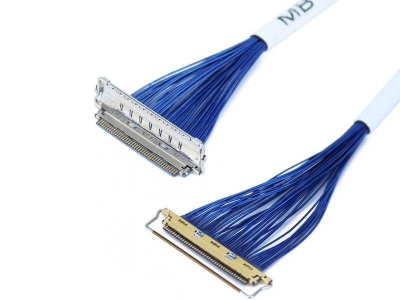
Read more →

In the fast-paced world of smartphone manufacturing, the demand for thinner micro-coaxial cables has become a crucial factor in driving innovation. As consumers continue to seek sleeker, more lightweight devices with enhanced functionality, smartphone manufacturers are constantly pushing the boundaries of design and engineering. This has led to an increased need for micro-coaxial cables that are not only thinner but also capable of delivering high-performance signal transmission. The Need for Thinner Micro-Coaxial Cables The primary reason behind smartphone manufacturers’ demand for thinne.

Read more →

(Perfectly optimized for SEO & user understanding) When you picture an autonomous vehicle (AV), you likely imagine sophisticated cameras, spinning LiDAR sensors, powerful processors, and complex AI algorithms. Rarely do we think about the miles of delicate wiring snaking through the car. Yet, hidden within these networks lies an unsung hero critical to making self-driving cars a reality: the ​micro-coaxial cable. Forget bulky wires; micro-coins represent the cutting edge. These are incredibly thin coaxial cables, often just millimeters wide. They possess a central conductor wrapped in insula.

Read more →

​High-Resolution Sensors: Encoders on closed-loop stepper motors (e.g., BLDC motors in advanced extruders). Precision temperature sensors (thermocouples) for heated chambers or nozzles. ​Signal-Intensive Components: Load cells (auto bed leveling strain gauges). High-speed camera feeds for monitoring/AI error detection. ​Why Coax Matters for Print Quality​ ​EMI/RFI Shielding: Coax blocks electromagnetic interference (EMI) from motors, heaters, and power cables. Without this, sensors can send false signals → layer shifts, thermal errors, or print failures. ​Signal Integrity: M.

Read more →

When it comes to data transmission, coaxial cables and fiber optics are two common options, but they have significant differences. Understanding these differences can help you choose the right one for your needs. Transmission Medium Coaxial cables use copper conductors to transmit electrical signals. This makes them rely on the flow of electrons for data transfer. In contrast, fiber optics use thin strands of glass or plastic to transmit data as light signals. The light travels through the fiber, bouncing off the walls due to a phenomenon called total internal reflection. Speed and Bandwid.

Read more →

Can't find what you're looking for?

Our customer support team is ready to assist you with any questions or concerns.

Search FAQs

Popular Tags

More Products

Our factory offers high-quality products at competitive prices

I-PEX Micro Coaxial Cable

I-PEX Micro Coaxial Cable

Overview of I-PEX Micro Coaxial Cable Connectors I-PEX is a global leader in micro coaxial cable solutions, specializing in high-performance IPEX micro coax connectors and micro coaxial cable assemblies. These products are designed for.

LVDS Micro Coaxial Cable

LVDS Micro Coaxial Cable

In LVDS (Low Voltage Differential Signaling) display systems, Micro-coaxial Cable (also referred to as Micro Coax Cable) stands out as an optimal solution for high-resolution, high-reliability signal transmission. Designed to meet the str.

Contact Us Micro Coaxial Cable factory-(FRS).


Feel free to reach out to us for any inquiries or orders

Call Us

Have a question? Give us a call!

+861881875005

Email Us

Send us an email and we'll get back to you soon.

sales@custom-cable-assemblies.com
       
Home Products Contact