Micro Coaxial Cable factory-(FRS)

automotive grade micro coaxial cable for display system - Micro Coaxial Cable factory-(FRS)

Micro Coaxial Cable factory-(FRS)

Micro coaxial cable Tag: automotive grade micro coaxial cable for display system

What Is Automotive Grade Micro Coaxial Cable for Display System and How Does It Work

Automotive display systems—from instrument clusters to pillar‑to‑pillar 4K/8Kpanoramic displays and HUDs—depend on high‑speed, low‑loss interconnects that survive the vehicle’s harsh environment. An automotive‑grade micro coaxial cable is a miniaturized, shielded transmission line built to carry video SERDES data (and sometimes power) through tight spaces with stable 50 Ωcharacteristic impedance, robust EMI performance, and deterministic loss over temperature and flex. Unlike consumer HDMI/DP, which are bulky for automotive use, these cables are designed for the automotive ecosystem: small diameter, high density, sealed interfaces, and tolerance to vibration, temperature, and EMC. Typical SERDES families like FPD‑Link IIIand GMSLuse coax or shielded twisted‑pair (STP) to move video, control, and even power over a single cable, enabling long runs and simplified harnessing in modern cockpits.

How It Works in a Display System

A display link starts at the source SoC/TCON serializer, which encodes video and control into a high‑speed serial stream. Over a micro coax, the signal travels to the display’s deserializer (DES), which recovers the video and back‑channel data. The cable’s job is to preserve eye opening and timing: its characteristic impedance must match the driver/receiver (nominally 50 Ωfor coax), and the assembly must minimize reflections (return loss), attenuation (insertion loss), and mode conversion (differential‑to‑common‑mode). Many automotive SERDES also implement Power‑over‑Coax (PoC), where a bias tee/filter network on each end superimposes DC power on the coax while isolating it from high‑speed data using frequency‑domain separation (FDM). Typical practice places data in higher bands (e.g., tens to hundreds of MHz and up) and control/return on lower bands (a few MHz), with inductors and capacitors forming a passive filter that presents high impedance to the data path while passing DC. This reduces线束 weight and connector count while maintaining signal integrity.

Key Electrical and Mechanical Parameters

  • Impedance and return loss: Coax is typically 50 Ω(differential pairs are 100 Ω); connectors and the transition region can introduce small mismatches, so both cable and connector must be specified for low return loss across the operating band.
  • Insertion loss and usable bandwidth: Loss rises with frequency (skin effect and dielectric loss); a given cable length has a usable bandwidth before the eye degrades. As a rule of thumb from published data, a 15‑mcoax may have about 3 GHzusable bandwidth supporting data rates up to roughly 6 Gbps, while a 10‑mshielded twisted‑quad (STQ) may reach about 2.5 GHzand ~5 Gbps. Designers size the channel (cable, equalization, and protocol margin) to keep the equalizer within its linear region.
  • Mode conversion and symmetry: In differential links, intra‑pair skew and amplitude imbalance cause mode conversion, which degrades SNR; high‑quality assemblies keep mode conversion well below insertion loss (by 10 dB or more).
  • Crosstalk: In multi‑pair or multi‑coax harnesses, far‑end and near‑end crosstalk rise with frequency; connectors and routing must control coupling.
  • In‑line connectors and harnessing: Each mated connector adds mismatch and loss; more in‑line connectors mean more return‑loss ripple and insertion‑loss variation. Harness routing, strain relief, and retention features are critical for automotive life.
  • Environmental: Automotive cables and connectors must withstand wide temperature swings, vibration, and flex. Qualification includes temperature cycling and mechanical stress to ensure stable performance over the vehicle’s lifetime.
automotive grade micro coaxial cable

Connector and Ecosystem Options

  • FAKRA and mini‑FAKRA (HFM): Widely used for automotive video/RF. Mini‑FAKRA (HFM) offers higher density and performance, with some solutions rated up to 20 GHzand multi‑port footprints that reduce PCB edge usage by up to 48%, suitable for high‑resolution displays and multi‑camera links.
  • GMSL coax ecosystem: GMSL1does not include PoC; GMSL2/GMSL3add integrated PoC, supporting data rates up to 12 Gb/sper cable for camera/display links across the vehicle.
  • FPD‑Link III coax: Supports single‑ended coax topologies with FAKRAconnectors for video and control; systems can run 4 Gbps and beyonddepending on cable quality, equalization, and length.
  • High‑speed miniature coax families: Vendor solutions such as TE’s MATE‑AXand IMS MCA/MCAHtarget ~9–20 GHzperformance in compact footprints for next‑gen displays and high‑bandwidth links.
  • Design note: Always impedance‑match the entire channel—cable, connector, and PCB launch—and verify return loss, insertion loss, and crosstalk jointly with the SERDES’ equalization capabilities.

Design Guidelines and Trade‑offs

  • Choose the right medium and topology: For very high bandwidth over longer runs, coax often wins; for dense, lower‑bandwidth links, shielded twisted‑pair (e.g., STQ/HSD) can be more economical. Match the medium to the SERDES family and target data rate.
  • Impedance control and connector discipline: Maintain 50 Ω(coax) end‑to‑end; minimize un‑twisting or shield removal at connectors; follow vendor layout/launch geometry to suppress return loss spikes.
  • Loss budgeting: Start with insertion‑loss vs. frequency data for the candidate cable, add connector loss and equalizer limits, then back‑calculate the maximum data rate and required equalization. Use the rule of thumb that a 15‑mcoax is roughly limited to ~6 Gbps, and a 10‑mSTQ to ~5 Gbps, adjusting for your specific cable and equalizer.
  • Symmetry and skew: Control pair geometry, length, and dielectric consistency to suppress mode conversion; measure intra‑pair skew during prototyping.
  • EMI and crosstalk: Use twisted‑pair or shielded quads where appropriate; separate high‑speed lanes; favor connectors with low crosstalk and robust shielding.
  • PoC design: Size bias inductors for the required DC current without saturating; keep the filter’s high‑frequency impedance high (e.g., >1 kΩ) to avoid loading the 50 Ωdata path; follow the SERDES’ reference filter topologies and frequency plan.
  • Environmental qualification: Plan for temperature cycling, vibration, and flex; qualify the complete harness, not just the raw cable.

Real‑World Examples and Data Rates

  • Pillar‑to‑pillar ultra‑wide displays: A 45–60‑inch, 7680 × 2160display can require roughly 28 Gbpsaggregate link bandwidth. Coax‑based SERDES (e.g., GMSL) are commonly used to carry such high data rates across instrument and display zones within the vehicle.
  • Typical link budgets: Coax SERDES links in the 4–12 Gbpsclass are common for in‑vehicle video; FPD‑Link III systems can exceed 4 Gbpsdepending on equalization and length.
  • Mini‑FAKRA/HFM for displays: High‑density, high‑frequency mini‑FAKRA systems (e.g., up to 20 GHz) are used where many high‑resolution video paths must be routed through compact, sealed connectors and PCB footprints.

Troubleshooting and Validation

  • Eye diagram and BER: Validate at the maximum operating temperature and minimum supply; check that the equalizer can compensate the cable’s loss slope without running out of margin.
  • Return loss and TDR: Use TDR to pinpoint impedance bumps at connectors, splices, or routing transitions; fix geometry or connector choice if return‑loss violations occur.
  • Mode conversion and skew: Measure differential‑to‑common‑mode conversion; if excessive, re‑route to equalize lengths, improve symmetry, or add common‑mode chokes at the receiver.
  • Crosstalk: Separate high‑speed lanes and avoid routing parallel to noisy sources; verify near‑end/far‑end crosstalk against spec at the highest frequency of interest.
  • PoC integrity: Check DC bias delivered to the remote module under load; verify that the bias filter does not degrade the data eye or create excessive common‑mode noise.

When to Choose Micro Coax vs. STP or Other Media

  • Choose micro coax when you need:
    • Deterministic, repeatable 50 Ωtransmission with excellent EMI control in a small diameter.
    • Longer runs than typical twisted‑pair at multi‑gigabit data rates.
    • Support for PoCin a single‑cable solution.
    • Sealed, robust interfaces for under‑hood or high‑vibration zones.
  • Choose shielded twisted‑pair (STQ/HSD) when:
    • You prioritize harness flexibility and density for medium‑bandwidth links.
    • The channel length is moderate and the SERDES/equalizer can close the link within your BOM budget.
  • Choose other media (e.g., Ethernet, optical) for specific cases: Ethernet for control/data aggregation, fiber for ultra‑long runs or extreme EMI environments—but video SERDES over coax remains dominant for in‑vehicle display interconnects due to maturity, cost, and integration.

Introduction to Micro-Coaxial Cables in 6G TechnologyMicro-coaxial cables are emerging as critical components in 6G communication systems, enabling high-speed data transfer, ultra-low latency, and reliable connectivity. As 6G networks aim to operate at terahertz (THz) frequencies and support advanced applications like holographic communication, autonomous systems, and IoT proliferation, the role of micro-coaxial cables becomes indispensable. This article explores their technical applications in 6G infrastructure and why they are vital for next-gen wireless networks. ​1. High-Frequency Signal Tr.

Read more →

In an era where precision and reliability are paramount, the packaging of coaxial cables has undergone a transformative overhaul to address the challenges of modern logistics, environmental sustainability, and end-user performance. This evolution is not merely cosmetic but a strategic response to industry demands for enhanced protection, cost efficiency, and adaptability. Let’s delve into the key innovations reshaping coaxial cable packaging and how they ensure these critical components arrive in pristine condition, ready to power industries from telecommunications to aerospace. The Limitations of .

Read more →

IntroductionArctic research stations face extreme cold, where temperatures plummet below -50°C. Standard electronics often fail under such conditions, disrupting critical data collection. To solve this, scientists now rely on cold-resistant micro-coaxial cables—a niche technology designed for reliability in polar environments. This article breaks down how these tiny yet robust cables keep Arctic science running. Key ApplicationsSensor NetworksMicro-coaxial cables connect weather stations, seismic monitors, and ice-penetrating radars. Their cold-resistant insulation (e.g., PTFE or aerogel composites.
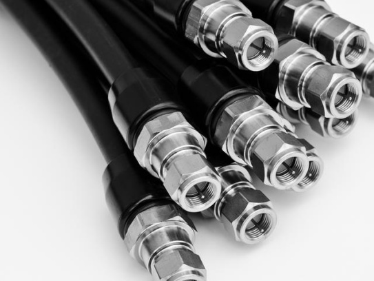
Read more →

In the realm of outdoor cable installations, ensuring reliable and efficient signal transmission is of utmost importance. One crucial component that plays a significant role in achieving this is the waterproof RF connector. These connectors are specifically designed to withstand the harsh environmental conditions that outdoor setups are exposed to, making them an essential choice for various applications. The Importance of Waterproof RF Connectors in Outdoor Settings Outdoor environments are fraught with challenges such as rain, snow, dust, and extreme temperatures. Standard RF connectors may no.

Read more →

In the highly competitive coaxial cable industry, our factory’s products have recently garnered widespread acclaim from industry experts, and their positive evaluations have become a hot topic in the market. A team of well-known experts specializing in communication technology conducted a comprehensive and rigorous test on our coaxial cables. In terms of signal transmission efficiency, the test results were remarkable. Under the same complex environmental conditions, our coaxial cables achieved a signal transmission efficiency of up to 97%, while the average level of similar products in the m.
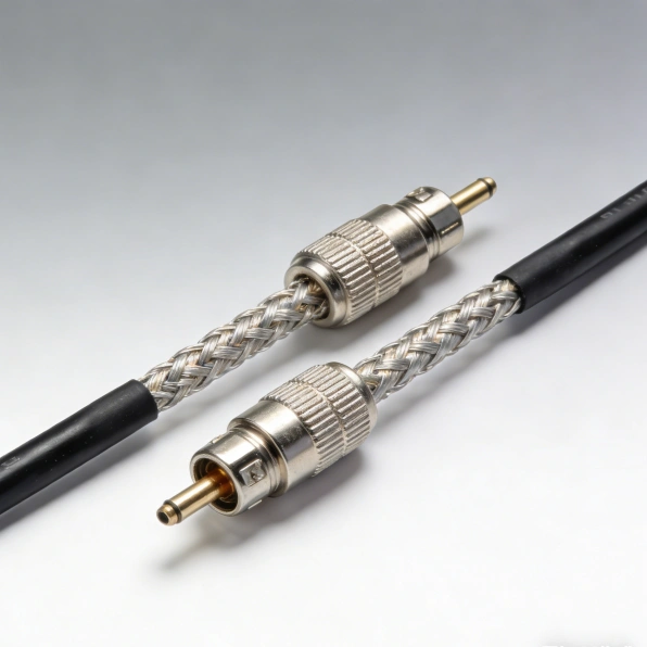
Read more →

In the dynamic world of drone technology, efficient and reliable communication is the linchpin for successful operations. Coaxial cable has emerged as a crucial component in ensuring seamless data transfer and stable connections for drones. This article delves deep into the significance, functionality, and applications of coaxial cable in drone communications. Understanding Coaxial Cable Coaxial cable is a type of electrical cable that consists of a central conductor, surrounded by an insulating layer, a metal shield, and an outer insulating layer. This unique construction allows for the efficie.

Read more →

Can't find what you're looking for?

Our customer support team is ready to assist you with any questions or concerns.

Search FAQs

Popular Tags

More Products

Our factory offers high-quality products at competitive prices

KEL Micro Coaxial Cable

KEL Micro Coaxial Cable

KEL’s Micro Coaxial Cable solutions are at the forefront of modern electronic connectivity, offering exceptional performance in high-speed data transmission, miniaturization, and reliability. These connectors are integral to various.

Industrial Micro-Coaxial Wiring

Industrial Micro-Coaxial Wiring

Meta Description: Discover the advanced features and benefits of Industrial Micro-Coaxial Wiring—engineered for precision, durability, and high-speed signal transmission in industrial environments. ​What is Industrial Micro-Co.

Contact Us Micro Coaxial Cable factory-(FRS).


Feel free to reach out to us for any inquiries or orders

Call Us

Have a question? Give us a call!

+8618818785005

Email Us

Send us an email and we'll get back to you soon.

sales@custom-cable-assemblies.com
       
Home Products Contact