Measuring the impedance of a micro coaxial cable is essential for ensuring signal integrity in high-frequency applications like medical devices, aerospace systems, smartphones, and compact RF modules. Unlike larger coax, micro coax (like 0.81mm, 1.13mm, or 1.37mm diameter cables) presents unique challenges due to its tiny size. Here’s a reliable, step-by-step method using professional equipment:
Why Micro Coax is Different:
- Extremely Small Conductors: Direct probe contact or clamping can easily deform the fragile center conductor and thin dielectric, invalidating the measurement.
- Shield Vulnerability: Even gentle pressure can displace the braid or foil shield, altering its impedance characteristics.
- Fixtures are Critical: Specialized test fixtures or connectors are almost always mandatory.
Equipment You’ll Need:
- Vector Network Analyzer (VNA): Essential for measuring complex impedance (magnitude and phase).
- Calibration Standards (Cal Kit): Precisely matched to the connectors you’ll use (e.g., SMA, 2.92mm, 1.85mm). Calibrate the VNA at the fixture planes.
- Test Fixtures (Crucial for Micro Coax):
- Jig/Launch Fixtures: Designed with precision grooves or clamps to hold the micro coax perfectly aligned without crushing it. Examples include GGB’s Picoprobe Model 40A/67A series or custom jigs.
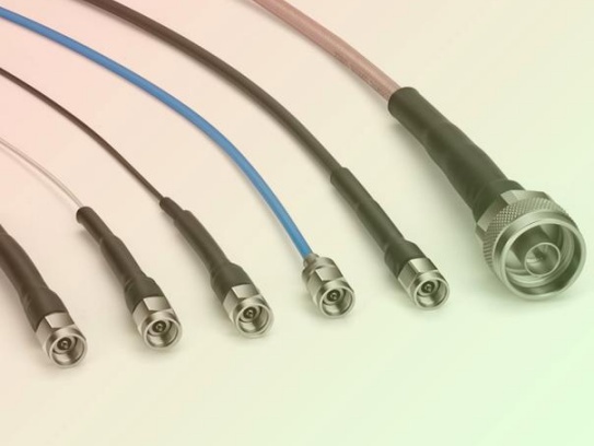
- Micro-Coaxial Connectors: Cable assemblies terminated with precision micro-coaxial connectors compatible with your VNA ports.
- RF Probes (e.g., Wafer Probes): Ground-Signal-Ground (GSG) or Ground-Signal (GS) probes with tip pitches matching the cable’s scale. Require extremely careful handling and specialized probe stations.
- Connectorization: Professionally soldering or crimping precision micro-coax connectors to the cable ends, providing stable VNA interfaces.
- Cable Preparation Tool: Sharp coax stripper specific to the exact cable size for clean, length-controlled access to center conductor and shield without nicking.
Step-by-Step Measurement Process:
- Prepare the Sample: Cut a clean length of micro coax. If using connectors, have them professionally installed per manufacturer specs. If using a jig/probe station, carefully prepare the cable ends: strip the jacket precisely to expose a controlled length of the shield, then carefully strip the dielectric to expose a controlled length of the center conductor, ensuring no deformation.
- Connect/Install in Fixture:
- **(Connectors):** Connect directly to VNA Ports 1 and 2.
- **(Jig):** Secure the prepared cable ends into the jig’s grooves or clamps following instructions. Crucial: Apply minimal pressure – just enough to ensure good electrical contact without deforming the cable structure.
- **(Probes):** Carefully lower the probes onto the prepared center conductor and shield points on each end. Use microscope alignment. Apply minimum pressure for contact.
- VNA Calibration: Perform a full 2-port calibration (SOLT – Short, Open, Load, Thru) at the point of contact. This removes errors from VNA, cables (if any), and test fixture up to the cable interfaces.
- For jigs/probes: Calibrate using standards mounted within the jig/probe station itself if possible, or directly at the probe tips.
- For connectors: Calibrate at the connector end-face.
- Measure S-Parameters:
- Set the VNA frequency range appropriate for your application (e.g., DC to 20+ GHz for many micro coax).
- Ensure the VNA sweep covers the relevant frequencies for your application.
- Measure the full 2-port S-parameters (S11, S21, S12, S22).
- Convert to Impedance (Z): Use the VNA’s built-in math functions:
- S11 to Input Impedance (Port 1): Measure S11. Use the VNA’s
S11 to Z function (or Smith Chart display). For a precise characteristic impedance (Z₀) measurement over a length, the method below is preferred.
- Calculating Characteristic Impedance (Z₀) Directly (Best Method): For a section of uniform line (your cable), Z₀ = √(Z_short * Z_open). Measure the cable with the far end terminated:
- Terminate the cable at Port 2 with a high-quality SHORT circuit. Measure the input impedance at Port 1 (
Z_short).
- Terminate the cable at Port 2 with a high-quality OPEN circuit. Measure the input impedance at Port 1 (
Z_open).
- Calculate:
Z₀ = sqrt(Z_short * Z_open). Modern VNAs often automate this calculation as a complex result across frequency.
- Review Results: Look at the Smith Chart or the complex Z trace (Real & Imaginary parts) vs. Frequency.
- Ideal Behavior: Z₀ should be relatively constant across the usable frequency range of the cable (specified by manufacturer). Real part should be near nominal (e.g., 50 Ohms), Imaginary part near 0 Ohms.
- Deviations: Large spikes, dips, or significant changes in Real/Imag parts indicate potential measurement errors (poor calibration, fixture issue) or cable defects. Consistent offset may indicate nominal impedance differs from target.
Key Considerations & Tips:
- Gentle Handling is Paramount: Micro coax measurement is an exercise in precision and care. Avoid any kinking, bending, or excessive force.
- Fixtures Determine Accuracy: The quality and correct usage of your jig, probes, or connectors determine the accuracy more than the VNA itself. Invest in good fixtures or accurate termination.
- Calibration is Sacred: Any calibration mistake ruins the measurement. Double-check standards and connections.
- Length Matters: For Z₀ calculation via short/open method, the cable section needs to be long enough to provide a clear measurement but not so long that losses dominate at high frequencies.
- Use Manufacturer Specs: Compare your measured Z₀ to the cable manufacturer’s specifications. Minor variations are normal, significant deviations suggest a problem.
- Reference Plane: Be mindful of where the calibration reference plane is set. You want it right at the cable interface.
- Alternative: TDR: Time Domain Reflectometry (TDR) with a sampling oscilloscope and suitable high-bandwidth fixture can measure impedance, but a VNA provides superior accuracy and frequency-domain insight for micro coax.
Conclusion:
Accurately measuring micro coax impedance requires specialized fixtures (jigs, probes, or precision connectors) and careful VNA calibration at the point of contact. Avoid direct clamping or probing of the fragile cable body. Prepare cable ends meticulously. Use the short/open termination method with your VNA’s S-parameter measurements and the calculation Z₀ = sqrt(Z_short * Z_open) for the most reliable determination of characteristic impedance across frequency. Precision, care, and good calibration are the keys to success. Always cross-reference your results with the cable manufacturer’s data sheet for your specific part number.