Micro coaxial cables (often called “micro coax”) are essential components for transmitting high-speed digital signals, RF signals, and low-level analog signals in modern electronics where space is constrained and signal integrity is paramount. Integrating them seamlessly onto a Printed Circuit Board (PCB) requires careful planning and execution. This comprehensive guide explores the critical steps and best practices for successful micro coaxial cable integration, ensuring robust performance and enhanced reliability in your designs.
Why Use Micro Coaxial Cables on PCBs?
Before diving into how, understanding the why is crucial:
Unrivaled Signal Integrity (SI): Micro coax provides superior electromagnetic interference (EMI) shielding compared to PCB traces, especially critical for:
High-speed serial interfaces (USB 3+/4, PCIe Gen 3/4/5, HDMI 2.1+, DisplayPort, Thunderbolt)
Sensitive analog signals (medical sensors, instrumentation).
Minimal Crosstalk: The outer shield effectively isolates the inner conductor from neighboring signals.
Impedance Control: Coax cables maintain a consistent characteristic impedance (e.g., 50Ω, 75Ω) along their length, critical for minimizing reflections.
Reduced Radiation: Significantly lower EMI emissions compared to exposed differential pairs or single-ended traces at high frequencies.
Flexibility: Micro coax allows routing between stacked boards, around components, or to external connectors/devices where rigid PCB routing is impossible or impractical.
Key Considerations for Integrating Micro Coax onto PCBs
Selecting the Right Micro Coaxial Cable:
Impedance: Match the cable’s impedance (50Ω or 75Ω are standard) to your source, destination, and PCB traces.
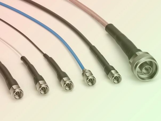
Size: Diameters range from ~0.4mm to ~2.0mm (e.g., RG-178, RG-316). Choose based on space constraints and required bend radius.
Frequency Range: Ensure the cable’s specified bandwidth exceeds your signal frequencies.
Shield Effectiveness: Look for cables with high braid or foil + braid coverage (e.g., >95%) for best EMI performance.
Flex Life: Critical for dynamic applications like robotics or foldable devices. Ensure sufficient durability.
Termination Compatibility: Verify available termination methods align with your PCB landing pad design.
PCB Stackup and Grounding Strategy:
Solid Reference Planes: Ensure continuous ground planes adjacent to the layers where coax connects. The shield must have a low-impedance path to ground.
Impedance Control: Design the trace leading from the micro coax termination point to the IC/connector to match the cable’s impedance. Use a field solver for accuracy.
Ground Vias: Strategically place numerous ground vias near the termination points to provide an ultra-low inductance return path for the shield currents and prevent ground loops. Use stitching vias around the connector footprint.
Termination Method: Precision is Key:
Solder Landing Pads: Design dedicated pads on the PCB surface layer.
Center Conductor Pad: Size for the inner pin/terminal; connect to the controlled impedance signal trace.
Shield Ground Pads: Design large, robust pads encircling the center pad (but electrically isolated) with thermal relief connections to the internal ground plane(s) only through the dense array of grounding vias.
Clearance: Maintain precise clearance between center pad and shield pads based on cable spec and soldering process tolerance. IPC standards are your friend.
Choice of Connector / Solder Method:
Board Mount Coaxial Connectors: (e.g., u.FL, SMP, MMCX, GPPO). Provide mechanical strain relief and precise mating. Design footprint exactly to manufacturer specs.
Direct Cable Soldering: Precise hand or automated soldering of the coax center conductor and shield wires/braid directly to the PCB pads. Requires skilled assembly and robust strain relief.
Surface Mount (SMT) Coax Connectors: Offer excellent repeatability for high-volume production.
Strain Relief: Non-Negotiable Reliability
Secure Attachment: Micro coax connections are fragile. Implement robust strain relief immediately adjacent to the solder joints.
Common Methods:
Epoxy: Apply a small amount of adhesive (compatible with the cable jacket) to bond the cable jacket to the PCB surface.
Cable Ties/Clips: Use dedicated surface-mount tie-down points or clips.
Strain Relief Features: Include hooks or posts molded into connectors.
Avoid Stress: Route the cable so bends start after the strain relief point, minimizing stress directly on the solder joints.
Routing and Placement:
Minimize Length: Keep coax runs as short as possible to minimize loss.
Bend Radius: Strictly adhere to the cable’s minimum bend radius spec, especially near termination points. Avoid sharp kinks.
Separation: Keep micro coax cables away from noise sources (switching regulators, clocks, digital buses) and sensitive circuitry when possible.
Shielding: Route cables away from cutouts or gaps in reference planes that compromise their shielding effectiveness. If cables cross plane splits, ensure the shield has a good ground path on both sides.
Service Loops (If Applicable): Leave a small service loop for future access or rework, but manage slack carefully.
Assembly Process: Critical for Success
Documentation: Provide clear assembly drawings and instructions specifying termination points, orientation, soldering method, and strain relief application.
Handling: Stress proper handling procedures to prevent cable damage during assembly.
Soldering: Skilled technicians are essential. Avoid excessive heat that damages cable dielectric or melts the jacket. Use appropriate flux and solder.
Inspection: Mandatory visual inspection (microscope recommended) and electrical testing (TDR for impedance checks, continuity, isolation tests) post-assembly.
Design Comparison Table: Micro Coax Integration
Design Aspect
Critical Consideration
Potential Pitfall
Impedance Matching
Match cable and trace impedance; use field solvers
Reflections, signal distortion, SI failures
Grounding
Low-impedance shield path; dense via stitching
Ground loops, ineffective shielding, EMI
Termination
Precision pad design; shielded solder joints
Weak connections; shorts; signal leakage
Strain Relief
Secure attachment at solder points
Broken connections from vibration/use
Bend Management
Maintain min. cable bend radius
Signal degradation; cable damage
Assembly
Skilled soldering; inspection protocols
Cold joints; overheating; connection failures
Advantages & Challenges
Advantages: Superior SI/EMI performance, consistent impedance, design flexibility, reduced crosstalk.
Integrating micro coaxial cables into PCB designs is a powerful strategy for overcoming the signal integrity challenges presented by high-speed and high-frequency applications. Success hinges on meticulous attention to detail: selecting the right cable, designing precise termination structures with exceptional grounding, implementing robust strain relief, carefully planning routing paths, and ensuring a highly controlled assembly process.
By mastering these techniques, PCB designers can leverage the benefits of micro coax to create compact, reliable, and high-performance electronic products that meet the demanding requirements of modern wireless communication, high-speed computing, medical devices, and aerospace systems. Carefully integrating these cables elevates your design from functional to exceptional in the realm of signal fidelity.
Ready to Elevate Your High-Speed PCB Designs? Consult with our signal integrity experts to ensure flawless micro coax integration in your next project!
Micro-coaxial cables are the unsung heroes of modern electronics, transmitting high-frequency signals in devices like routers, medical equipment, and aerospace systems. However, over time, these tiny cables can degrade due to wear, envi...
When working with coaxial cable assemblies, one of the most common questions engineers, technicians, and procurement professionals ask is: “Are coaxial cable assemblies compatible with all connector types?” The short answer is no—compat...
In today’s technology-driven world, Coaxial Cable Assemblies serve as the backbone of signal transmission in countless industries—from telecommunications and aerospace to medical equipment and industrial automation. These assemblies, wh...
Laboratory equipment, such as spectrum analyzers, signal generators, and network analyzers, relies heavily on precise signal transmission to ensure accurate test results. Coaxial cable assemblies serve as the critical link in this proce...
Micro coaxial cables are widely used in various electronic devices due to their excellent signal transmission capabilities and compact size. However, soldering micro coaxial cable connections can be a tricky task, especially for beginne...
As the global rollout of 5G technology accelerates, the demand for reliable, high-performance infrastructure has never been greater. Among the key components powering 5G networks, 5G small cells stand out—they enable dense cov...
The answer is a resounding yes. Coaxial cable assemblies are indispensable components in broadcast television systems, playing a critical role in ensuring the reliable, high-quality transmission of audio and video signals throughout the...
In high-speed electronics and radio frequency (RF) designs, reliably moving signals from point A to point B without distortion or loss is critical. Two common ways to achieve this are Micro Coaxial (Micro-Coax) Cables and Microst...
Venturing into the deep ocean is one of humanity’s greatest technological challenges. Deep-sea Remotely Operated Vehicles (ROVs) are our eyes and hands in these crushing depths, enabling scientific discovery, resource exploration,...
The question of whether coaxial cable assemblies are used in gaming consoles is one that resonates with tech enthusiasts, gamers, and industry professionals alike. To answer it directly: yes, coaxial cable assemblies play a crucial role...
Micro-coaxial cables (micro-coax) – those thin, often less than 3mm diameter cables – are the unsung heroes powering critical video, RF, and data signals in drones, cameras, medical devices, and countless electronics. But their delicate...
When sourcing micro-coaxial assemblies for electronics, medical devices, or telecommunications systems, businesses often face a critical decision: Should they bulk-purchase raw materials and build in-house, or buy pre-made assemblies f...
Coaxial cable assemblies are the backbone of high-frequency communication systems, enabling reliable signal transmission in applications ranging from telecommunications and aerospace to medical devices and industrial automation. Their a...
In the relentless push for smaller, faster, and more powerful electronics – from cutting-edge medical devices and aerospace systems to next-gen telecommunications and high-resolution imaging – high-density micro-coaxial cable bundles&n...
Micro coaxial cables are the tiny workhorses powering signals in countless devices: your smartphone’s camera, medical implants, drones, high-frequency test equipment, and complex aerospace systems. Choosing reliable micro coax is ...
Introduction: The Critical Role of Impedance MatchingIn the high-speed, high-frequency world of modern electronics – encompassing everything from sophisticated medical devices to ubiquitous smartphones and intricate aerospace systems – ...
Choosing the right micro coaxial cable for aerospace isn’t just about performance; it’s about absolute reliability in the harshest environments imaginable. Aircraft, satellites, and spacecraft demand components that can with...
AbstractSignal interference remains a critical challenge in high-frequency applications using micro-coaxial cables, impacting performance in 5G devices, medical imaging systems, and aerospace electronics.
IntroductionMicro-coaxia...
Tangled cables don’t just look messy—they can slow you down, create tripping hazards, and even damage equipment over time. Whether you’re setting up a home office, gaming station, or entertainment center, effective cable management is k...
Ordering bulk quantities of coaxial cable assemblies is a critical process that directly impacts project timelines, budget efficiency, and overall performance of electronic systems. Whether you’re sourcing for telecommunications, aerosp...
In the vast expanse of the ocean, reliable communication is the lifeline for marine and offshore operations. Whether it’s for ship navigation, offshore drilling platforms, or marine research vessels, seamless data transfer and cle...
Selecting the right dielectric material for micro coaxial cables is critical for high-frequency performance, reliability, and cost-effectiveness. Polytetrafluoroethylene (PTFE) and Polyethylene (PE) are the two dominant contenders. Unde...
In the rapidly evolving landscape of electronic devices and communication systems, the demand for high-performance signal transmission solutions has never been more critical. Among the various components that enable seamless data and si...
The relentless hum, the powerful thuds, the constant tremors – heavy machinery operates in a world dominated by vibration. While essential for demanding industrial tasks, this vibration poses a silent, pervasive threat to the intricate...
In high-speed, high-density electronic systems, micro coaxial cableis often the critical link that determines whether your product performs reliably in the field or fails during EMI/EMC testing.
At FRS, we design and manufacture high...
In the realm of modern communication and electronic systems, coaxial cable assemblies stand as a cornerstone technology, playing a pivotal role in transmitting signals with reliability and efficiency. Among the key performance metrics t...
The future of reliable connectivity in demanding environments just took a quantum leap forward. A groundbreaking patent for self-healing micro-coaxial cables has been officially filed, promising to dramatically reduce failures, ext...
The relentless drive towards smaller, lighter, and more capable military systems places immense pressure on every component – especially the critical infrastructure connecting them: cables. Enter the spotlight: Battlefield-Ready Micro-...
In the world of outdoor electrical and communication setups, the significance of a reliable cable cannot be overstated. When it comes to harsh weather conditions, outdoor-rated coaxial cables emerge as the go-to solution for a plethora ...
In the rapidly evolving world of energy storage systems (ESS), efficiency, reliability, and safety are non-negotiable. Whether it’s for large-scale grid storage, renewable energy integration, electric vehicle charging infrastructu...
The evolution from traditional power grids to intelligent Smart Grid Systems demands a robust, reliable, and high-performance communication infrastructure. At the heart of this critical communication layer lies a proven and essential ...
(Perfectly optimized for SEO & user understanding)
When you picture an autonomous vehicle (AV), you likely imagine sophisticated cameras, spinning LiDAR sensors, powerful processors, and complex AI algorithms. Rarely do we think ...
The question of whether coaxial cable assemblies can be used in high-pressure environments is a critical one for industries ranging from oil and gas to marine exploration, aerospace, and industrial manufacturing. The short answer is yes...
Passive Intermodulation (PIM) has long been a critical challenge in high-frequency communication systems, where even minute unwanted signals can disrupt signal integrity and degrade network performance. Micro-coaxial cables, widely used...
RF cable assemblies are critical components in telecom infrastructure, enabling reliable signal transmission across networks. From 5G base stations to data centers, these assemblies connect antennas, transceivers, and other equipment, d...
Ever looked at a blurry X-ray or a fuzzy ultrasound and worried about accurate diagnosis? In the high-stakes world of medical imaging, clarity is crucial. One unsung hero powering this precision is the micro-coaxial cable. These tiny ...
In the competitive landscape of the coaxial cable industry, customer satisfaction stands as the cornerstone of business success. For coaxial cable customers, encountering issues with products or services can be frustrating, and the way ...
In the era of rapid development of 5G communication, satellite navigation, and high – speed data transmission, coaxial cables, as the core medium for signal transmission, face increasingly strict requirements for high – freq...
What Are Medical Ultra-Fine Coaxial Cables?Ultra-fine coaxial cables are specialized cables designed for high-frequency signal transmission in compact environments. Unlike standard coaxial cables, they feature:
Microscopic Diameter...
Modern cars are becoming marvels of electronic intelligence, largely thanks to Advanced Driver Assistance Systems (ADAS) like automatic emergency braking, adaptive cruise control, and blind-spot monitoring. At the heart of many of...
H1: Precision Instrument Micro-Coax – Engineered for Critical Signal Integrity
Meta Description: Discover Precision Instrument Micro-Coax: Miniature coaxial cable solution optimized for high-frequency signal transmissio.
IntroductionIn today’s fast-paced digital world, reliable and high-speed data transmission is critical for industries ranging from telecommunications to aerospace. Enter High-Speed Data Micro-Coax—a cutting-edge miniature coaxial cable e.
Contact Us Micro Coaxial Cable factory-(FRS).
Feel free to reach out to us for any inquiries or orders