How to Properly Document Micro Coaxial Cable Test Results - Micro Coaxial Cable factory-(FRS)
Micro Coaxial Cable factory-(FRS)
INFO
Documenting micro coaxial cable test results accurately is crucial for quality control, troubleshooting, failure analysis, and ensuring reliable performance in your applications. Proper documentation creates a clear record for anyone reviewing the data now or in the future. Here’s a step-by-step guide focusing on what matters most:
Tester Name/ID: Person(s) who performed the tests.
Location: Where testing was conducted (if relevant).
Instrumentation Used: List the key test equipment (e.g., “VNA: Keysight N9918A”, “LCR Meter: Fluke PM6306”, “TDR: Tektronix DSA8300”, “Cable Tester: MultiContact CrimpStar IV”).
Cable Specification & Identification:
Manufacturer & Part Number: (e.g., “CompanyX – MCX-042-50-SS”)
Detailed Cable Spec: Impedance (50Ω or 75Ω), core conductor material/gauge (e.g., “26AWG Silver Plated Cu”), dielectric type (e.g., “Foamed PTFE”), shield construction (e.g., “Dual Shield: Braid + Foil”), outer jacket material (e.g., “PVC”), overall diameter (e.g., “1.13mm”).
Cable Length Being Tested: Specify precisely (e.g., “1.00 meter”).
Cable Sample Identifier/Lot/Batch Number: Essential for traceability.
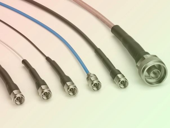
Connector Types: Specify the connectors on each end precisely (e.g., “End A: U.FL (IPX)”, “End B: MMCX”).
Connector Termination Quality Notes: Any observations during visual inspection before electrical testing.
Test Setup Details:
Test Configuration Sketch/Diagram: (Highly Recommended) Even a simple sketch showing:
Test equipment inputs/outputs.
Cable under test orientation.
How connectors interface to fixtures/test ports (e.g., “End A -> VNA Port 1 via SMA(f)-U.FL(m) adapter”). Include model numbers of key adapters/fixtures.
If using a reference plane or calibration type.
Calibration: Record calibration method used (e.g., “SOLT Calibration performed on VNA Ports 1 & 2 to SMA(f) interface plane prior to test”) and date of last calibration.
Test Parameters: Specific settings on the instruments:
VNA/TDR: Start/Stop Frequency, Number of Points (or Resolution), IF Bandwidth, Averaging Factor, Power Level. Especially for TDR: Pulse Rise Time, Acquisition Time.
LCR Meter: Test Frequency (e.g., “1 MHz”), Test Signal Level (e.g., “1V RMS”).
Environmental Conditions: Temperature and Humidity (if controlled or significantly deviating from standard lab conditions).
Connector Torque: If torque wrenches are used for mating connectors to test ports, note the applied torque (e.g., “U.FL mating: Finger tight only”, “SMA adapter mating: 8 in-lbs”).
Measured Test Results:
Test Specification: Clearly state the specification/standard each test relates to (e.g., “Insertion Loss < 0.8 dB @ 6 GHz per MIL-DTL-17” or “DC Resistance < 0.5 Ohms/m per Manufacturer Spec Sheet”).
Recorded Values: For each test performed:
Continuity & Shorts: “Pass” (Open between center/shield, continuity along center, shield continuity established) OR detailed description of any failure.
DC Resistance: Value measured at each conductor (Center Conductor Ω/m or Ω total; Shield Ω/m or Ω total).
Capacitance (pF/m or pF total): Measured value.
Insulation Resistance: Value measured (e.g., “> 1000 MΩ @ 500VDC”) and test voltage/duration.
Insertion Loss/Attenuation: Results at specified frequency points, especially maximum operating frequency and critical intermediate points. (e.g., “0.65 dB @ 1 GHz”, “1.05 dB @ 6 GHz”). Plotting is ideal, but tabulate key points.
Return Loss / VSWR: Results at specified frequency points. (e.g., “Return Loss: 18 dB @ 6 GHz” or “VSWR: 1.25:1 @ 6 GHz”).
Propagation Delay: Measured value (e.g., “4.85 ns/m”).
Delay Skew (if applicable): Between conductors in a multi-cable assembly.
Structural Return Loss (SRL) / Impedance Profile: Key observations from TDR trace (e.g., “Impedance average: 51.2Ω”, “Maximum deviation: ±2.5Ω”, location of any significant anomalies).
Bend Radius Test Results: Document the test radius used (per specification), number of flex cycles, Pass/Fail status with failure criteria, and any performance measurement taken after testing (e.g., “Loss after 1000 bends: +0.15dB @ 6GHz vs pre-bend”).
Conclusion & Review:
Pass/Fail Status: Clear statement: “All tests passed specifications” or “Failed: Shield DC Resistance exceeded limit – See Test #DCR-S02”.
Approvals: Space for signatures/dates of test engineer and reviewer.
Attachment Reference: If plots or detailed data files are generated, reference them clearly here (e.g., “See attached file: MCX-042-Batch_Plots.pdf”).
Formatting Tips for Clarity:
Use Tables: Organize results logically. Have separate tables for Cable Info, Test Setup, and Result Data.
Be Specific: Instead of “Connector”, write “U.FL (IPX)”. Instead of “Low Loss”, write “Insertion Loss = 0.72 dB @ 6 GHz”.
Plot Graphs: Where trends matter (like Loss/RL vs. Frequency), graphs are essential. Ensure axes are clearly labeled. Save plots as images or PDFs linked to the report.
Notes Section: Add a section for any relevant observations not captured elsewhere (e.g., “Minor shield fraying noted at End A during connector visual – did not affect electrical results”).
Electronic & Physical Copies: Store securely. Ensure digital filenames are descriptive and include date/lot number.
Sample Results Table Snippet:
Test Parameter
Specification
Measured Value
Unit
Frequency (if app.)
Result
Notes
Cable ID
MCX-042-50-SS-Lot#123A
Length: 1.00m, Conn: UFL-MMCX
Continuity
Open: CC-Shield Cont: CC, Shield
Pass
Pass
Visual: No damage
DC R – Center Cond.
< 0.20 Ω/m
0.18
Ω/m
Pass
DC R – Braid Shield
< 0.05 Ω/m
0.042
Ω/m
Pass
Insertion Loss
≤ 0.80 dB @ 6GHz
0.72
dB
6.0 GHz
Pass
Fig. 1
Return Loss
≥ 18 dB @ 6GHz
19.5
dB
6.0 GHz
Pass
Fig. 1
Bend Radius Test
10x Cable OD, 1000 cycles
Pass
Loss Δ @6GHz: +0.10dB
(Add more rows as needed)
Common Mistakes to Avoid:
Missing Traceability: No cable part number, lot number, or unique sample ID.
Unclear Test Setup: Not documenting adapters, calibration reference plane, or torque makes replication impossible.
Reporting Only “Pass/Fail”: Losing the actual measured values provides no detail for future analysis or trend spotting.
Vague Results: Reporting “Insertion Loss: Good” instead of specific values at specific frequencies.
Missing Frequency Points: Not reporting loss/RL at the cable’s maximum specified operating frequency.
Ignoring Visuals: Failing to document pre-existing physical damage can lead to incorrect failure attribution later.
Ignoring Test Conditions: Not recording temperature/humidity or specific instrument settings can make data hard to interpret or compare later.
No Summary/Conclusion: Forcing the reader to hunt through all data to determine if the cable passed overall requirements.
Disorganized Presentation: Scatter information, making the report hard to follow.
Coaxial cables are indispensable in modern communication, security surveillance, and broadcast systems, enabling stable signal transmission in homes, enterprises, and industrial sites. As manufacturers expand globally—penetrating market...
Micro coaxial cables are the unsung heroes of modern military electronics. Packing powerful signal capabilities into an ultra-thin profile, they’re essential for everything from missile guidance systems and radar to ruggedized com...
Miniature coaxial cables are essential components in modern electronics, telecommunications, and high-frequency applications. Whether you’re designing a medical device, a military communication system, or a consumer gadget, choosing the...
When designing or troubleshooting RF (Radio Frequency) systems, the choice between 50Ω and 75Ω micro-coaxial cables often sparks confusion. While both are widely used in electronics and telecommunications, their performance ...
The Fourth Industrial Revolution, Industry 4.0, is transforming manufacturing. Smart factories hum with interconnected devices: sensors constantly gather data, robots execute precise movements, and complex machinery communicates in real...
Micro coaxial cable assemblies are widely used in compact electronics, medical devices, industrial sensors, and automotive systems where space constraints and reliability are critical. Their IP (Ingress Protection) rating is essential f...
In the intricate ecosystem of medical equipment, where precision and reliability can directly impact patient outcomes, the role of high-performance connectivity solutions cannot be overstated. Our coaxial cables, specifically engineered...
Coaxial cable assemblies are critical components in telecommunications, aerospace, industrial automation, and consumer electronics, transmitting high-frequency signals with minimal interference. However, corrosion—caused by moisture, ch...
There is no fixed weight for standard coaxial cable assemblies, as it is determined by multiple key factors. Understanding these factors and practical weight references is crucial for engineers, purchasers, and anyone involved in select...
Ever wonder why signal timing is critical in high-speed electronics like 5G phones, radar systems, or advanced medical imaging? A key player hiding within your micro coaxial cables is propagation delay – the time it takes for an e...
In the high-stakes world of modern military operations, mission-critical communication is the cornerstone of coordination, intelligence gathering, and command execution. But what happens when a powerful electromagnetic pulse (EMP)...
In the complex web of modern electronic systems, ensuring seamless signal compatibility is a fundamental challenge. Signals come in diverse forms—analog and digital, with varying frequencies, amplitudes, and protocols—yet they often nee...
The question of whether coaxial cable assemblies are compatible with fiber optic systems is a common one among engineers, IT professionals, and system integrators tasked with building or upgrading communication networks. In short, coaxi...
Micro coaxial cable soldering service is a specialized capability that joins ultra‑fine coaxial conductors to connectors or PCB pads with precise impedance control, mechanical reliability, and high‑frequency signal integrity. It is wide...
In the world of electrical and networking installations, coaxial cables play a crucial role. They are widely used in applications such as cable television, satellite TV, CCTV systems, and high – speed internet connections. When it...
Electric Vehicles (EVs) promise a cleaner, quieter future, but their complex high-voltage battery packs require constant, precise monitoring to ensure safety, performance, and longevity. At the heart of this critical task lies the Batte...
The short answer is a resounding yes—coaxial cable assemblies are not only compatible with smart home devices but also play a crucial role in enhancing the performance, reliability, and stability of modern smart home ecosystems. As smar...
Introduction: The Need for Speed at the Edge
Edge computing is revolutionizing how we process data. By bringing computation closer to where data is generated – sensors, IoT devices, cameras, machines – it slashes the time wasted send...
Coaxial cable assemblies are critical components in industries like telecommunications, aerospace, and medical equipment, where signal integrity and reliability directly impact system performance. Certification serves as a guarantee tha...
Coaxial cable assemblies are critical components in countless electronic systems, from telecommunications and aerospace to medical devices and industrial automation. Their performance directly impacts the reliability, signal integrity, ...
The recent publication of the Coaxial Cable Market Research Report marks a critical resource for industry stakeholders—from manufacturers and suppliers to procurement managers and technology investors. As a foundational compon...
Introduction
In today’s rapidly evolving technological landscape, custom coaxial cable assemblies are critical for industries demanding high-performance connectivity. Whether for aerospace, military, telecommunications, or medical eq...
IntroductionHigh-frequency micro-coaxial cables are critical components in modern electronics, enabling reliable signal transmission in applications like telecommunications, medical devices, aerospace systems, and high-speed data networ...
Meta Description: Learn how to calculate the velocity factor in micro-coaxial cables step-by-step. Improve signal integrity and optimize high-frequency designs with this essential guide.
Introduction
Velocity factor (VF)...
Neural recording technology has revolutionized our understanding of the brain’s complex functions, enabling breakthroughs in neuroscience research, clinical diagnostics, and neuroprosthetics. At the heart of this technology lies a criti...
As the Internet of Things (IoT) evolves from a niche concept to a global infrastructure, the demand for smaller, more reliable, and high-performance components has never been greater. Among these critical components, micro-coaxial cable...
In high-speed, high-density electronic systems, micro coaxial cableis often the critical link that determines whether your product performs reliably in the field or fails during EMI/EMC testing.
At FRS, we design and manufacture high...
In the modern healthcare system, a stable and efficient network is not just a support system but a critical component that directly impacts patient care, medical workflow, and data security. Hospitals handle massive volumes of sensitive...
Military-grade micro-coaxial cables are critical components in defense systems, aerospace technology, and advanced communication networks. At the heart of their performance lies the dielectric material, which ensures signal integrity, ...
Micro coax cable is widely used in high-frequency signal transmission, but many engineers and buyers still struggle with unstable performance, high loss, and inflexible customization when sourcing from different suppliers. As a professi...
1. High-Frequency Signal Fidelity Supports Ultra-High Frequency Transmission: Micro coaxial cables can reliably transmit high-frequency signals up to 40 GHz, meeting the bandwidth requirements of high-definition audio (e.g., 24-bi...
In the fast-evolving world of medical technology, devices like implantable sensors, MRI machines, and surgical robots rely on precision-engineered components to function safely and accurately. Among these components, medical-grade micr...
In the realm of electronic connections, coaxial cables with gold-plated connectors stand out for their enhanced conductivity, playing a vital role in numerous applications.
Coaxial cables have a unique structure that enables them to ...
The global micro-coaxial cable market is experiencing dynamic growth, driven by advancements in high-frequency signal transmission and miniaturized electronics. Recent research highlights key trends shaping this niche but critical secto...
In our interconnected world, micro coaxial cables are vital in various applications. Ensuring their signal quality is crucial for system functionality. This article offers key insights and practical guidance on testing.
Why is Testin...
Coaxial cables are indispensable in high-speed data transmission, industrial automation, and telecommunications infrastructure—their performance directly determines the reliability of end-use systems. However, traditional coaxial cable ...
When working with delicate electronics or high-frequency signal applications, precision is non-negotiable. For 0.81mm micro-coaxial cables—commonly used in medical devices, aerospace systems, and telecommunications—a reliable crimping t...
The global transition toward smart grids is revolutionizing how we generate, distribute, and consume utilities. At the heart of this transformation are Advanced Metering Infrastructure (AMI) systems, commonly known as smart metering sys...
As display resolutions, refresh rates, and color depths continue to climb, the demand for stable, high-bandwidth video transmission has never been greater. For many OEMs and system integrators, the micro coaxial cable for DisplayPort hi...
Microwave links play a pivotal role in modern communication systems, enabling high-speed data transmission across long distances without the need for physical fiber-optic cables or terrestrial wiring. From telecommunications networks an...
H1: Precision Instrument Micro-Coax – Engineered for Critical Signal Integrity
Meta Description: Discover Precision Instrument Micro-Coax: Miniature coaxial cable solution optimized for high-frequency signal transmissio.
Meta Description: Discover the advanced features and benefits of Industrial Micro-Coaxial Wiring—engineered for precision, durability, and high-speed signal transmission in industrial environments.
What is Industrial Micro-Co.
Contact Us Micro Coaxial Cable factory-(FRS).
Feel free to reach out to us for any inquiries or orders