
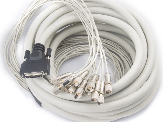
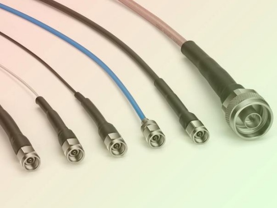
Micro Coaxial Cable factory-(FRS)
In high-speed electronics and radio frequency (RF) designs, reliably moving signals from point A to point B without distortion or loss is critical. Two common ways to achieve this are Micro Coaxial (Micro-Coax) Cables and Microstrip Transmission Lines. While both serve the same fundamental purpose, they differ significantly in structure, application, and performance. Understanding these differences is key to selecting the best option for your project.
Core Structure & Concept:
Key Differences:
Here’s a breakdown of how they compare across critical factors:
| Feature | Micro Coaxial Cable | Microstrip Transmission Line |
|---|---|---|
| Structure | Miniature cable assembly (inner conductor, insulator, shield, jacket) | PCB Etched trace over dielectric over ground plane |
| Integration | External component; requires connectors/soldering | Integral part of the PCB fabrication |
| Shielding | Excellent. Full 360° shielding prevents signal radiation and external interference. | Limited. Ground plane shielding on one side only; susceptible to radiation/crosstalk above and to the sides. |
| Signal Isolation | Exceptional. Signals in different micro-coaxes are highly isolated from each other. | Good within layer, Poor across layers. Highly dependent on spacing, guard traces, and via shielding. |
| Loss @ High Freq. | Generally Lower. Especially at higher frequencies (> 10s of GHz), lower dielectric loss and controlled impedance result in less signal attenuation per unit length. | Generally Higher. Dielectric losses in the PCB material and skin effect losses become significant at very high speeds/frequencies. |
| Impedance Control | Tight & Stable. Manufactured with precise geometry for specific impedance (e.g., 50Ω, 75Ω). | Good, but Varied. Requires careful trace width design and relies on consistent dielectric thickness/constant. More susceptible to etching variations and nearby structures. |
| EMI Radiation | Very Low. Fields are contained within the shield. | Noticeable. Fields extend above the trace; can radiate and cause interference or emissions issues. |
| Crosstalk | Very Low. Excellent shielding minimizes coupling. | Higher Risk. Requires careful trace spacing, ground plane management, and sometimes guard traces to minimize coupling between adjacent traces. |
| Dispersion | Lower. Generally better performance for broadband signals. | Higher. Velocity changes slightly with frequency, potentially distorting very broadband signals. |
| Complexity/Cost | Higher. Cost per unit length + cost of connectors + assembly complexity. | Lower. Minimal added cost over standard PCB fabrication (cost is in design effort and potentially higher-end materials). |
| Routing Flexibility | High & Low. Flexible cables route freely around the board, but connectors/terminations restrict direct point-to-point integration. | Integrated & Constrained. Routing is limited to the PCB surface layers; requires vias to change layers, impacting signal integrity. |
| Density | Lower. Cables occupy physical space above the board; challenging to route densely. | Higher. Enables dense routing of traces on the PCB surface layer(s). |
| Best Suited For | External connections, connecting instruments, high-frequency/high-isolation requirements between boards/modules, extreme noise environments. | On-board routing for high-speed digital (PCle, USB, DDR, Ethernet) & RF signals (up to 10s of GHz), cost-sensitive designs where PCB integration is paramount. |
When to Choose Which?
The Blurring Line: Embedded (Coaxial-like) Stripline
While microstrip dominates PCBs and micro-coax dominates external cabling, there’s overlap. Advanced designs might use “Stripline” (traces sandwiched between two ground planes in inner PCB layers) for better shielding than microstrip. Newest techniques like embedded coaxial routes channels within the PCB with barrel-shielded vias, offering integrated micro-coaxial-like performance directly on the board for speeds above 50 GHz.
Conclusion:
Micro coax cables and microstrip transmission lines are both vital tools. Micro coax offers superior shielding and signal integrity performance, especially at very high frequencies and for external connections, but at a higher cost and complexity. Microstrip provides a cost-effective and highly integrated solution for routing high-speed signals directly on PCBs, requiring careful design to mitigate its inherent shielding limitations and losses at very high frequencies. The best choice depends entirely on your specific application’s performance, integration, cost, and environmental requirements.
Our factory offers high-quality products at competitive prices
Meta Description: Discover our premium Flexible Micro-Coaxial Assemblies—engineered for high-frequency signal integrity, durability, and versatility in aerospace, medical, telecom, and robotics applications. What Are Flexible .
H1: Precision Instrument Micro-Coax – Engineered for Critical Signal Integrity Meta Description: Discover Precision Instrument Micro-Coax: Miniature coaxial cable solution optimized for high-frequency signal transmissio.
Feel free to reach out to us for any inquiries or orders