How to Calculate Signal Attenuation in Micro Coaxial Cables (The Practical Guide) - Micro Coaxial Cable factory-(FRS)
Micro Coaxial Cable factory-(FRS)
INFO
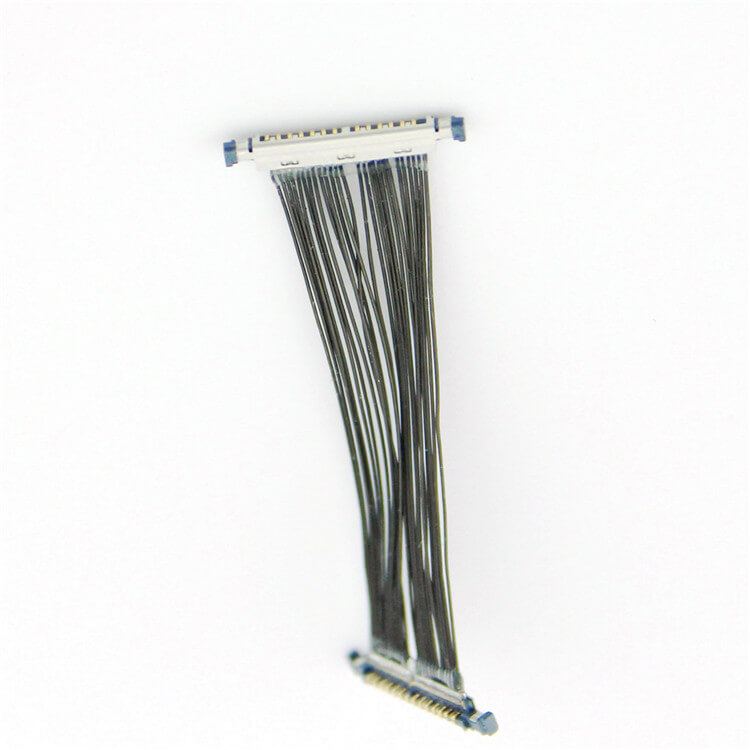
Signal attenuation – the gradual weakening of a signal as it travels through a cable – is a critical factor in any high-frequency electronic system. When working with micro coaxial cables, their small size makes understanding and calculating attenuation absolutely essential for reliable performance, especially in applications like drones, medical devices, communications, and densely packed electronics. This guide breaks it down clearly.
Understanding Attenuation: The Basics
Imagine shouting down a long hallway. Your voice gets quieter the further away the listener is. Similarly, an electrical signal traveling through a micro coax cable loses energy as heat and electromagnetic radiation, resulting in a weaker signal at the far end compared to the input. This loss is measured in decibels (dB).
The key things impacting attenuation in micro coax are:
Frequency (f): The single biggest factor! Attenuation increases significantly with higher frequencies. A signal at 6 GHz will lose much more power over the same distance than one at 100 MHz. This is due to complex effects like skin effect and dielectric loss scaling with frequency.
Cable Length (L): Signal loss accumulates over distance. Attenuation is directly proportional to cable length. Doubling the length roughly doubles the loss (in dB).
Cable Construction: This defines the cable’s inherent lossiness per unit length. Key elements are:
Conductor Material & Size: Copper is standard. Larger center conductors generally have lower resistance and thus lower attenuation (especially at lower frequencies/smaller diameters).
Dielectric Material: The insulator between the center conductor and shield. Materials like Polyethylene (PE), PTFE (Teflon), or Foamed variants have different inherent loss tangents. Foam dielectrics typically offer lower attenuation than solid equivalents.
Shield Construction: While primarily for EMI protection, multiple braids or braid+foil shields can slightly impact attenuation characteristics compared to simpler shields.
Precision of Construction: Consistency is vital for stable performance.
The Core Formula for Calculation
Attenuation (often denoted as α or IL for Insertion Loss) is typically given in decibels per unit length (most commonly dB per meter (dB/m) or dB per 100 feet (dB/100ft)) at a specific frequency.
The most reliable and simplest way to calculate total attenuation for a specific cable length at a specific frequency is:
Total Attenuation (dB) = Attenuation per Unit Length (dB/m or dB/ft) × Cable Length (m or ft)
Where Do You Get the “Attenuation per Unit Length”?
This is the crucial piece! You get it directly from the cable manufacturer’s datasheet. Reputable manufacturers provide detailed graphs or tables showing attenuation vs. frequency for their specific micro coax products.
Look for Charts: Most datasheets have a graph titled “Attenuation vs. Frequency” or similar. The Y-axis is attenuation (dB/m or dB/100ft), the X-axis is frequency (Hz, MHz, GHz). Find your operating frequency on the X-axis, trace up to the curve, and read the dB/m value on the Y-axis.
Look for Tables: Some datasheets provide attenuation values at specific key frequencies (e.g., 100 MHz, 1 GHz, 3 GHz, 6 GHz, 10 GHz).
Example Calculation:
Scenario: You’re using a micro coax cable specified to have an attenuation of 0.5 dB/m at your operating frequency of 5 GHz.
Cable Length: Your assembly requires a cable length of 0.25 meters.
Calculation: Total Attenuation = 0.5 dB/m * 0.25 m = 0.125 dB
Interpretation: You expect your signal to lose approximately 0.125 dB of power over this 25cm length at 5 GHz. (Note: This seems small, but at GHz frequencies and longer lengths, losses add up significantly).
Important Considerations & Why Datasheets are King
Frequency Dependence: NEVER assume attenuation is constant! The value 0.5 dB/m from our example is ONLY valid at 5 GHz. At 10 GHz, the attenuation per meter for the same cable will be much higher (maybe 0.9 dB/m or more). Always use the attenuation value corresponding to YOUR specific operating frequency.
Length Matters: While calculated loss might seem small for short jumpers, longer cable runs demand strict attention. Losses compound quickly (e.g., 1.0 dB/m * 2.0 m = 2.0 dB loss).
Datasheet Specificity: Use the datasheet for the EXACT cable model and gauge you are using. Different cable models (even from the same manufacturer) and different diameters (e.g., 0.81mm vs. 1.37mm) have vastly different attenuation characteristics. Don’t rely on generic estimates!
Connector Loss: The calculation above is for the cable alone. Connectors also introduce loss (typically between 0.1 dB and 0.5 dB or more per connector, depending on type, frequency, and quality). For a cable assembly with connectors on both ends, you need to add their attenuation to the cable’s loss: Total Assembly Loss ≈ Cable Loss + Connector 1 Loss + Connector 2 Loss
Skin Effect: At high frequencies, current flows mostly on the surface (“skin”) of the conductor, increasing its effective resistance and thus attenuation. This is inherently factored into the datasheet values.
Dielectric Loss: Energy absorbed by the dielectric material itself. This is also frequency-dependent and built into the datasheet.
Copper Roughness: The microscopic roughness of the inner conductor surface can significantly increase attenuation at very high frequencies (GHz+). High-quality cables minimize this.
Practical Steps to Calculate Your Micro Coax Attenuation
Identify Your Cable: Know the exact manufacturer, part number, and AWG/diameter.
Locate the Datasheet: Download the official, up-to-date datasheet from the manufacturer’s website.
Find Attenuation Data: Locate the “Attenuation vs. Frequency” chart or table.
Determine Your Frequency: Identify your signal’s operating frequency (e.g., 2.4 GHz, 5.8 GHz, 10 GHz).
Read dB/m (or dB/ft): From the chart/table, find the attenuation value at your specific frequency.
Measure Your Cable Length: Know the exact length of the micro coax cable section you are analyzing.
Calculate: Multiply the dB/m value by your cable length (in meters). If the datasheet uses dB/100ft, convert length to feet first or convert dB/100ft to dB/ft (/100).
Add Connector Losses (if applicable): Estimate or find specifications for the loss of each connector used and add them. If precise figures are unknown, budgeting 0.2-0.3 dB per connector is a reasonable starting point for many micro-coax connectors at moderate GHz frequencies.
Beyond Calculation: Tips for Minimizing Attenuation in Micro Coax Designs
Choose the Right Cable: Select a micro coax model specifically designed for your frequency range. Larger diameter cables generally have lower attenuation than smaller ones, but trade off flexibility and size.
Optimize Dielectric: Opt for low-loss dielectrics like foamed PTFE where possible.
Minimize Length: Keep cable runs as short as the design physically allows.
Use High-Quality Connectors: Precise, well-matched connectors minimize added loss and reflections (VSWR).
Avoid Tight Bends: Sharp bends distort the cable geometry, increasing loss. Adhere to the manufacturer’s specified bend radius.
Consider Active Components: For very long runs or extremely high frequencies where cable loss is prohibitive, amplifiers (re-drivers) might be necessary.
Conclusion
Calculating signal attenuation in micro coaxial cables isn’t guesswork; it’s a precise process relying on manufacturer datasheets. Remember the core formula: Total Cable Attenuation (dB) = Attenuation per Unit Length (dB/m) × Cable Length (m), making sure to use the value corresponding to your exact cable model, specific operating frequency, and measured length. Don’t forget to factor in connector losses for the complete picture. By accurately calculating and minimizing attenuation, you ensure your high-frequency signals arrive with sufficient strength for your micro coax applications to perform reliably. Always consult authoritative datasheets for the most accurate and reliable information.
The question of whether coaxial cable assemblies are resistant to water and moisture does not have a simple “yes” or “no” answer. Their resistance largely depends on design, materials, and manufacturing processes...
In commercial, industrial, and residential buildings, cables penetrate walls, floors, and ceilings to enable essential services like power, data, and communication. However, these penetrations create pathways for fire, smoke, and toxic ...
When sourcing micro-coaxial assemblies for electronics, medical devices, or telecommunications systems, businesses often face a critical decision: Should they bulk-purchase raw materials and build in-house, or buy pre-made assemblies f...
Understanding the Challenge
Micro-coaxial cables (often called “micro-coax”) are essential for high-frequency signal transmission in medical devices, aerospace systems, and 5G infrastructure. However, signal degradation o...
Coaxial cable assemblies are critical components in countless applications, from telecommunications and aerospace to medical equipment and industrial automation. Their ability to transmit high-frequency signals with minimal interference...
Robotic arms are marvels of modern engineering, designed to perform precise, repetitive tasks in industries like manufacturing, healthcare, and automation. At the heart of their functionality lies their wiring system, particularly flex...
Is your military communication system acting up? A damaged micro-coaxial cable could be the culprit. These tiny cables are the unsung heroes of military tech, carrying vital signals in radios, radar systems, and encrypted communica...
In the dynamic world of outdoor broadcasting, where every moment of live transmission matters, the quality and reliability of the equipment used are of utmost importance. One such crucial component is the weatherproof coaxial cable. Thi...
When shopping for coaxial cables, one of the most common questions is: “How much does one meter of coaxial cable cost?” While prices vary based on factors like quality, type, and brand, this guide breaks down everything you ...
Coaxial cable assemblies are indispensable in industries like telecommunications, aerospace, automotive, and medical equipment. Their ability to transmit high-frequency signals with minimal interference directly determines the performan...
AbstractSignal interference remains a critical challenge in high-frequency applications using micro-coaxial cables, impacting performance in 5G devices, medical imaging systems, and aerospace electronics.
IntroductionMicro-coaxia...
Micro coaxial cables are critical components in high-frequency and high-speed systems, from 5G infrastructure to medical imaging devices. However, selecting the right cable requires balancing technical specifications, environmental dema...
Autonomous drones have revolutionized industries ranging from aerial photography and agriculture to logistics and industrial inspection. Behind their seamless operation lies a network of critical components, and micro-coaxial cables sta...
Introduction
Micro-coaxial cables are essential for transmitting high-frequency signals in compact spaces, but harsh environments with constant vibrations (e.g., aerospace, automotive, or industrial machinery) demand specialized desi...
Ensuring the reliability and performance of micro coaxial cable assemblies before they are integrated into your system is critical. Faulty cables can lead to system failures, costly downtime, and difficult troubleshooting late...
Ever nervously plugged in your e-scooter charger on a damp day, hoping rain doesn’t sneak into the connection? Or worried about corrosion wrecking your precious charger’s plug? That tiny connector between your charger cable ...
Military applications demand electronic components that can withstand extreme conditions while maintaining uncompromised performance—coaxial cable assemblies are no exception. These critical components serve as the backbone of communica...
The question of whether coaxial cable assemblies are compatible with fiber optic systems is a common one among engineers, IT professionals, and system integrators tasked with building or upgrading communication networks. In short, coaxi...
Industrial control systems (ICS) are the backbone of modern manufacturing, energy, transportation, and infrastructure sectors, relying heavily on stable and reliable signal transmission to ensure operational efficiency and safety. Among...
The answer to whether coaxial cable assemblies can be used in home theater systems is a resounding “yes.” In fact, coaxial cable assemblies have long been a reliable and practical choice for various connections within home t...
Imagine downloading a full HD movie in a blink, or medical scanners delivering crystal-clear images instantly during life-saving procedures. The relentless surge of data in our world – from streaming services and cloud computing to arti...
In satellite communications—where signals travel across thousands of kilometers of space and face extreme environmental stress—micro-coaxial cables (micro-coax) serve as critical “neural links.” Unlike standard coaxial cable...
A significant milestone has been reached in our factory’s history as we proudly announce the successful mass production of our high – performance coaxial cables. This achievement is not just a result of months of hard work b...
For ham radio operators and amateur communicators, the coaxial cable is far more than a “connecting wire”—it is the lifeline of signal integrity. A poorly chosen or installed coaxial cable can lead to significant signal loss...
Forget bulky cables and signal dropouts. If you’re navigating the rapidly evolving landscape of factory automation – deploying robotics, vision systems, or complex sensor networks – you’ve likely encountered the critica...
Your car’s advanced safety features – automatic emergency braking, adaptive cruise control, blind-spot monitoring – rely heavily on invisible eyes: radar sensors. These sensors, increasingly operating at high frequencies like 76-81 GHz,...
In the third quarter of 2024, our factory achieved a major milestone in the Southeast Asian market—our coaxial cable sales hit 120,000 units, marking a 45% year-on-year growth and setting a new regional sales record. This breakthrough i...
You use Starlink for video calls, streaming, or staying connected off-grid. But have you ever wondered how thousands of satellites overhead work flawlessly in the brutal environment of space? One unsung hero is surprisingly sm...
What Are Medical Ultra-Fine Coaxial Cables?Ultra-fine coaxial cables are specialized cables designed for high-frequency signal transmission in compact environments. Unlike standard coaxial cables, they feature:
Microscopic Diameter...
Overview and definition
A micro coaxial cable with an I-PEX 20373 connector is a miniaturized, shielded interconnect built to carry high‑speed differential or single‑ended signals between tightly spaced PCBs or modules. The I‑PEX 203...
In the world of outdoor electrical and communication setups, the significance of a reliable cable cannot be overstated. When it comes to harsh weather conditions, outdoor-rated coaxial cables emerge as the go-to solution for a plethora ...
AbstractPhase stability—the ability of a cable to maintain consistent signal phase characteristics under varying conditions—is a critical yet often overlooked parameter in micro-coaxial cable design. This article examines the factors in...
Choosing micro-coil cable seems straightforward: pick the specs, find a supplier, install it. But here’s the industry secret seasoned project managers know: ignoring reel length during procurement is one of the costliest mistakes...
The relentless drive towards smaller, lighter, and more capable military systems places immense pressure on every component – especially the critical infrastructure connecting them: cables. Enter the spotlight: Battlefield-Ready Micro-...
The short answer is a resounding yes—coaxial cable assemblies, especially high-performance Micro-Coaxial Cables, are not only compatible with DVR (Digital Video Recorder) systems but also serve as a critical component in ensuring reliab...
In the complex web of modern connectivity, coaxial cables stand as vital arteries, carrying critical signals across a vast array of industries. From the bustling floors of manufacturing plants to the high – speed realm of aerospac...
Meta Description: Learn how to calculate the velocity factor in micro-coaxial cables step-by-step. Improve signal integrity and optimize high-frequency designs with this essential guide.
Introduction
Velocity factor (VF)...
In the world of broadcasting, nothing frustrates listeners or viewers more than a distorted signal. Interference can ruin the entire experience, whether it’s static on a radio, pixelation on a TV, or dropped audio in a live stream. Achi...
OverviewMicro-Coax for HD Video is a cutting-edge coaxial cable engineered to deliver uncompromised high-definition video quality across professional and industrial applications. Designed for reliability, precision, and versatility,.
Meta Description: Discover our premium Flexible Micro-Coaxial Assemblies—engineered for high-frequency signal integrity, durability, and versatility in aerospace, medical, telecom, and robotics applications.
What Are Flexible .
Contact Us Micro Coaxial Cable factory-(FRS).
Feel free to reach out to us for any inquiries or orders