Is your military communication system acting up? A damaged micro-coaxial cable could be the culprit. These tiny cables are the unsung heroes of military tech, carrying vital signals in radios, radar systems, and encrypted communication links. Replacing them requires precision, but with the right knowledge, it’s achievable. This guide provides clear, actionable steps to safely replace a damaged micro-coaxial cable in military equipment.
Why is this Important?
- Mission Readiness: Faulty cables compromise critical communication and sensor systems.
- Signal Integrity: Proper installation ensures clear data transmission, vital for situational awareness.
- Safety: Correct procedures prevent damage to expensive equipment and potential hazards.
- Reliability: Military operations demand equipment that functions flawlessly under pressure.
Before You Begin: Safety & Preparation is Key
- Consult the Manual (TM): ALWAYS refer to the specific Technical Manual (TM) for your equipment. It contains vital safety warnings, approved parts lists, and exact procedures. Never skip this step.
- Power Down & Secure: Completely power down the equipment and disconnect it from all power sources (batteries, generators, mains). Follow Lockout/Tagout (LOTO) procedures if applicable.
- ESD Protection: Military electronics are sensitive. Wear a grounded anti-static wrist strap connected to a proper grounding point on the equipment chassis.
- Gather Tools & Parts:
- Replacement Cable: Obtain the exact part number specified in the TM. Military cables have specific impedance (often 50 ohms), shielding, and connector types. Using the wrong cable can cause failure.
- Precision Tools: Needle-nose pliers, fine tweezers, small screwdrivers (flathead & Phillips), torque wrench (if specified for connectors).
- Cleaning Supplies: Isopropyl alcohol (IPA), lint-free swabs.
- Magnification: A magnifying lamp or headset is essential for seeing tiny connectors and wires.
- Documentation: Pen and paper or camera to document existing wiring before disassembly.
Step-by-Step Replacement Process
- Identify & Access:
- Locate the damaged cable using diagnostics outlined in the TM or visual/physical inspection (look for kinks, cuts, crushed sections, melted insulation, damaged connectors).
- Carefully remove any panels, covers, or components necessary to access both ends of the cable and its routing path. Note screw locations and types.
- Document & Disconnect:
- Photograph/Draw: Take clear pictures or make a sketch showing exactly how the cable is routed and connected at both ends. Note any cable ties, clamps, or strain reliefs.
- Label (Optional but Recommended): If complex, use small labels or tape to mark connectors or ports.
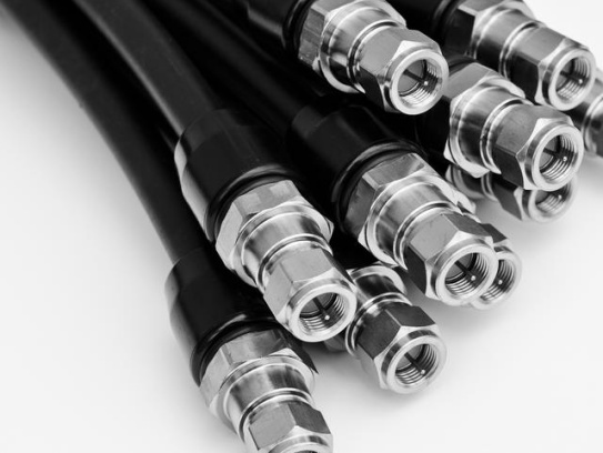
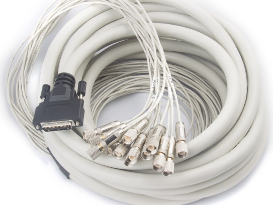
- Disconnect: Gently disconnect the cable at both ends. Note the connector type (SMA, TNC, etc.) and orientation. Some connectors require unscrewing, others may have locking clips – release them carefully.
- Remove the Damaged Cable:
- Carefully remove any cable ties, clamps, or adhesive securing the cable along its path. Avoid putting stress on other components.
- Gently pull the cable free, following its original route in reverse. Be mindful of sharp edges or pinch points.
- Prepare the Replacement Cable & Connectors:
- Inspect: Check the new cable for any defects before installation.
- Clean (If Needed): Use IPA and lint-free swabs to gently clean the mating connectors on the equipment if they appear dirty or contaminated. Allow to dry completely.
- Handle with Care: Avoid kinking or sharply bending the new cable. Micro-coax is fragile.
- Route & Connect the New Cable:
- Follow the Path: Route the new cable exactly along the same path as the old one. This is crucial for preventing EMI/RFI interference and physical damage.
- Secure: Reinstall all cable ties, clamps, and strain reliefs exactly as the original was secured. Ensure the cable isn’t pulled taut or pinched. Leave a slight service loop if possible/appropriate.
- Connect: Attach the cable connectors to their respective ports firmly but do not overtighten. Finger-tight is usually sufficient for most micro-coax connectors unless the TM specifies a torque value. Ensure connectors are fully seated and properly oriented (check your photos/sketch!).
- Reassemble & Power Up:
- Carefully replace all panels, covers, and components removed for access, ensuring all screws are replaced correctly.
- Double-check that all tools and debris are removed from the equipment.
- Reconnect power sources.
- Test Thoroughly:
- Power on the equipment according to the TM.
- Perform all operational checks and diagnostic tests specified in the TM for the affected system (e.g., radio check, radar self-test, data link verification).
- Monitor for any signal degradation, noise, or intermittent faults.
Critical Considerations for Military Applications
- Traceability: Ensure the replacement cable comes from a certified source and its part number is logged in maintenance records.
- EMI/RFI Shielding: Military environments are electrically noisy. Correct routing and connector seating are vital to maintain the cable’s shielding integrity.
- Environmental Seals: Some military connectors have environmental seals (o-rings). Ensure these are intact and properly seated during connection.
- Vibration & Strain: Military equipment experiences harsh conditions. Proper clamping and strain relief are non-negotiable to prevent future failures.
- Calibration: Replacing cables in sensitive RF systems (like radar) may require recalibration. Consult the TM.
When to Call a Professional
- If the TM explicitly states the procedure requires certified personnel.
- If the damage is near sensitive components (e.g., inside a sealed RF module).
- If you lack the specific tools, ESD protection, or environment.
- If the system fails operational checks after replacement.