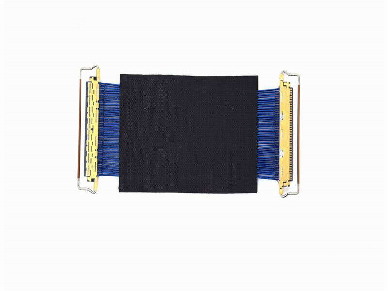
Within the intricate world of high-frequency electronics and RF systems, consistency is paramount. For signals traveling multiple pathways simultaneously – such as in phased array antennas, beamforming networks, power combiners/dividers, or critical instrumentation setups – the timing and phase relationship between signals are crucial. This is where phase matching in micro coaxial cable assemblies becomes a non-negotiable requirement.
The Critical Need for Phase Matching
At microwave and millimeter-wave frequencies, electrical lengths become incredibly short relative to signal wavelengths. Even minute physical variations in cable assemblies translate directly into significant phase shifts. When phase differences exist between signal paths:
Signal Cancellation/Reduction: Coherent signals arriving out-of-phase can destructively interfere, drastically reducing output power (e.g., in power combiners).
Beam Distortion: In phased array systems, unmatched phase delays across radiating elements steer the antenna beam in unintended directions or create distorted side lobes.
Measurement Errors: In test setups like vector network analyzers comparing device responses across multiple channels, unmatched cables introduce phase offsets that corrupt data.
System Degradation: Mismatched paths in transceiver modules, satellite payloads, or any multi-channel system can significantly degrade overall performance metrics like signal-to-noise ratio (SNR), error vector magnitude (EVM), and data throughput.
Phase matching specifically refers to the requirement that the electrical phase delay at a specified frequency (or across a specified bandwidth) be virtually identical for two or more coaxial cable assemblies within a system or bundle.
Key Requirements Dictating Phase Match Performance
Achieving precise phase matching in micro coaxial assemblies demands meticulous attention to several core aspects:
Physical Length Matching:
The Foundation: Cable physical length is the most fundamental factor affecting electrical length and thus phase delay. A difference in physical length translates directly to a difference in electrical length at a given frequency (Phase Difference (°) ≈ 360 * (ΔElectrical Length / Wavelength)).
Precision Required: Tolerances for matched assemblies are often extremely tight. While absolute lengths vary per application, the difference in length between a set must be minimized, typically specified with precision like ±0.10mm, ±0.05mm, or even finer (±0.025mm or ±0.010″). “Cut-to-length” precision is non-negotiable. Bundles must be cut simultaneously under tension to ensure uniformity.
Dielectric Material Uniformity:
Velocity Factor Consistency: The speed of the electromagnetic wave propagating down the cable is slower than in free space, determined by the velocity of propagation (Vp) or velocity factor (VF), which depends primarily on the insulation’s dielectric constant (εr). VF = 1 / √εr.
Consistency is Key: The dielectric material’s εr must be exceptionally uniform not only along the length of each individual cable but also identical between cables within a matched set. Any variation in εr directly impacts VF and thus the electrical length at a given physical length.
Low-Density Foam Dielectrics: Often preferred for phase-stable assemblies due to the inherent consistency achievable and their lower overall εr (e.g., ~1.45-1.55), resulting in higher velocity factors.
Stable Phase vs. Temperature:
Temperature Dependence: Materials expand and contract with temperature (Coefficient of Thermal Expansion – CTE). More critically, the dielectric constant (εr) of the insulator changes with temperature (Temperature Coefficient of Dielectric Constant – TCDk). Both effects alter the electrical length.
Requirement: Phase-matched assemblies must exhibit minimal relative phase drift over their operating temperature range. This demands cables with inherently low TCDk materials and construction techniques that minimize differential thermal effects (e.g., stable jacket materials, consistent bundling).
Minimized Bend-Induced Phase Effects:
Bend Impact: Bending a cable locally disturbs the electromagnetic field distribution within the dielectric and around the center conductor. This perturbation changes the effective electrical path length (phase delay) at the bend location. Tight bends or bends applied differently to cables in a bundle introduce phase differences.
Stable Routing Requirement: Phase-matched assemblies require careful installation with controlled, consistent, and gentle bend radii. Cable assemblies designed for minimal phase deviation under bending are often specified. Bundled sets should be dressed identically.
Connector and Termination Repeatability:
End-to-End Delay: The connectors themselves contribute a fixed electrical length to the overall assembly.
Precision Assembly Mandate: Connector attachment must be highly repeatable and precise. Variations in the pin/contact depth relative to the connector reference plane or minor soldering inconsistencies can introduce small but significant phase differences between otherwise identically prepared cables. Rigorous process control ensures connector-induced delay is consistent.
Quantifying Phase Match: Tolerances
Phase matching tolerance is always specified at one or more specific frequencies. Common metrics include:
Phase Tracking: e.g., “±0.03°/GHz from 6-18 GHz” (phase difference between cables changes minimally over frequency).
Absolute Phase Difference: The maximum allowed phase angle difference between any two assemblies within a matched set at the specified frequency(s).
Group Delay Matching: Often related, as constant group delay implies stable phase vs. frequency.
Typical Tolerances in Precision Assemblies
Application Level
Typical Phase Match Tolerance Example
Standard
±10° – ±15° @ Specific Frequency
Good
±5° @ Specific Frequency
High Precision
±3° – ±2° @ Specific Frequency
Very High Precision
±1° – ±0.5° @ Specific Frequency
Extremely High Precision
< ±0.5° @ Specific Frequency
(Note: Tolerances are highly frequency-dependent; tighter tolerances are significantly harder to achieve at higher frequencies due to shorter wavelengths.)
Critical Testing and Measurement
Verifying phase match is non-trivial and requires specialized equipment and methods:
Network Analyzer Setup: A calibrated Vector Network Analyzer (VNA) with multiple test ports is essential.
Reference Plane: Testing requires establishing a precise, stable reference plane for comparison. This often involves using phase-matched reference cables or a carefully calibrated setup to normalize the measurement.
Differential S-Parameters: The most accurate measurement involves using the VNA in multi-port mode to directly measure the differential phase (S21 phase) between cables. Alternatively, carefully normalized measurements can be compared.
Temperature Chambers: Verifying phase match under thermal stress necessitates environmental chambers capable of cycling temperature while performing VNA measurements.
Applications Driving the Requirement
Phased Array Radar/Antenna Systems (Military, SATCOM, 5G/6G): For accurate beam pointing and control.
Microwave Power Combining/Division Networks: Essential for maximizing combiner efficiency.
Instrumentation: Multi-port VNA setups, test fixtures, phase-sensitive measurements.
Satellite Payloads: Where redundancy and signal routing accuracy are vital.
Electronic Warfare (EW) Systems: Beamforming, direction finding.
Advanced Communications Transceivers: MIMO systems, massive MIMO.
Medical Imaging Systems (e.g., High-Field MRI RF Coils): Require precise phase coherence between elements.
Radio Astronomy Arrays: Signal correlation accuracy.
Specifying Phase-Matched Micro Coaxial Assemblies
When procuring phase-matched assemblies, provide clear specifications including:
Number in Set: How many cables need to be matched (e.g., pair, quad, set of 8).
Precise Operating Frequency Range: Or specific frequency(s) of interest.
Required Phase Match Tolerance: Including target specification and frequency point(s).
Phase Tracking Requirement (if needed): Specifying how phase difference should behave over frequency.
Operating Temperature Range: For which the phase match must be maintained.
Required Bend Radius (if known): Impacts achievable tolerance.
Length(s): Specify if absolute length matters, or if only match tolerance is critical.
Conclusion
Phase matching in micro coaxial cable assemblies is a demanding engineering requirement critical to the performance of advanced RF and microwave systems. Achieving it demands precision in cable manufacturing (dielectric uniformity), precise assembly (length control, connector repeatability), stable low-TCDk materials, and careful handling. Understanding the fundamental requirements—physical length match, dielectric consistency, phase stability over temperature, and controlled bending effects—is essential for specifying, designing, and integrating systems where phase coherence determines success. When multiple signal paths must behave as one, phase-matched cables are the indispensable foundation.
Meta Description: Discover why micro-coaxial cables are critical for 5G networks, renewable energy systems, medical imaging, and autonomous vehicles. Explore their key technical advantages and industry-specific use cases.
Why ...
Coaxial cable assemblies are widely used in communication, aerospace, medical equipment, and other fields, and their connector performance directly affects signal transmission quality. Over time, dust, oil, oxidation, and other contamin...
Military applications demand electronic components that can withstand extreme conditions while maintaining uncompromised performance—coaxial cable assemblies are no exception. These critical components serve as the backbone of communica...
Keeping micro coaxial connectors (like BNC, SMA, SMB, MCX, MMCX) clean is crucial for strong, reliable signals in cameras, medical devices, test equipment, and communications gear. Dirt, dust, oils, or oxidation can cause fuzzy pictures...
Micro coaxial cable soldering service is a specialized capability that joins ultra‑fine coaxial conductors to connectors or PCB pads with precise impedance control, mechanical reliability, and high‑frequency signal integrity. It is wide...
As the global rollout of 5G technology accelerates, the demand for reliable, high-performance infrastructure has never been greater. Among the key components powering 5G networks, 5G small cells stand out—they enable dense cov...
Meta Description: Discover the best miniature coaxial cables for underwater robots. Learn about durability, waterproofing, and performance factors to ensure reliable subsea operations.
Underwater robots, such as remotely ope...
Q: What’s the typical capacitance per foot for micro coaxial cables?
A: There isn’t one single “typical” value applicable to all micro coaxial cables. However, for common thin micro coax cables like RG178 or s...
Particle accelerators, like the famous Large Hadron Collider (LHC) at CERN or smaller synchrotrons and linear accelerators worldwide, are engineering marvels pushing the boundaries of physics. They smash particles together at nearly the...
Coaxial cable, often recognized by its distinctive round shape and threaded metal connector (F-type or BNC), might seem like a relic from older CCTV systems. Yet, coaxial cable remains a relevant, reliable, and often preferable choice&...
In the high-stakes world of modern military operations, mission-critical communication is the cornerstone of coordination, intelligence gathering, and command execution. But what happens when a powerful electromagnetic pulse (EMP)...
Looking for reliable information on micro coax cable installation? You’ve come to the right place. Micro coaxial cables (often abbreviated as “micro coax”) are the lifeblood of modern high-frequency electronics. F...
Coaxial cable assemblies are critical components in industries like telecommunications, aerospace, and medical equipment, where signal integrity and reliability directly impact system performance. Certification serves as a guarantee tha...
AbstractCoaxial cables are a cornerstone of modern communication systems, but their design and functionality differ significantly from other cable types such as twisted-pair, fiber-optic, and ribbon cables.
1.IntroductionCables serv...
The short answer is a resounding yes—coaxial cable assemblies are not only compatible with smart home devices but also play a crucial role in enhancing the performance, reliability, and stability of modern smart home ecosystems. As smar...
Micro-coaxial cables (“micro-coax”) are the unsung heroes of modern electronics, carrying high-frequency signals critical for everything from 5G phones and medical devices to drones and high-speed data links. But their tiny ...
In the intricate ecosystem of data centers, where every component plays a critical role in maintaining seamless operations, coaxial cable assemblies stand as unsung heroes. These specialized cables facilitate the transfer of high-freque...
In the vast expanse of modern satellite communications, where signals need to traverse incredible distances with utmost precision, micro – coaxial cables have emerged as a crucial component. These cables, smaller in diameter compa...
Underground installation of communication and signal transmission cables is a common practice in many industries, from telecommunications and broadcasting to industrial automation and security systems. However, choosing the right cable ...
When selecting micro-coaxial cables for high-temperature applications, understanding the temperature tolerance of PTFE-insulated micro-coaxial cables is critical. Polytetrafluoroethylene (PTFE) is a popular insulation material due...
Our factory’s coaxial cable R&D team has recently clinched a prestigious industry award, a well-deserved recognition of their relentless efforts and outstanding innovations in the field.
The award, presented by a leading au...
Modern cars are becoming marvels of electronic intelligence, largely thanks to Advanced Driver Assistance Systems (ADAS) like automatic emergency braking, adaptive cruise control, and blind-spot monitoring. At the heart of many of...
n an era defined by lightning-fast connectivity and shrinking electronic devices, micro coaxial cables have emerged as unsung heroes powering the seamless flow of data. These miniature yet mighty cables are engineered to meet the escala...
Introduction
In today’s rapidly evolving technological landscape, custom coaxial cable assemblies are critical for industries demanding high-performance connectivity. Whether for aerospace, military, telecommunications, or medical eq...
In the world of broadcasting, nothing frustrates listeners or viewers more than a distorted signal. Interference can ruin the entire experience, whether it’s static on a radio, pixelation on a TV, or dropped audio in a live stream. Achi...
The rapid evolution of 5G technology has brought about a paradigm shift in wireless communication, with Multiple-Input Multiple-Output (MIMO) technology standing as a cornerstone for achieving the high data rates, low latency, and massi...
Ever experienced frustrating video lag during an important video call? Watched pixelation ruin a live sports stream? Or encountered mysterious errors in high-tech medical equipment? Often, the unseen culprit lies in the cables strugglin...
Introduction to Coaxial Cables
Coaxial cable (or coax) remains one of the most reliable transmission mediums for high-speed internet and television signals. Originally developed in the 1880s and perfected throughout the 20th century,...
Introduction
Micro-coaxial cables have become the backbone of modern high-frequency signal transmission, from medical devices to 5G networks. Since 2000, shielding techniques have undergone revolutionary changes to meet escalating de...
In the realm of public safety communications, reliability and performance are non-negotiable. Coaxial cables have long been a cornerstone in ensuring seamless and secure transmission of data, voice, and video, playing a crucial role in ...
When it comes to data transmission, coaxial cables and fiber optics are two common options, but they have significant differences. Understanding these differences can help you choose the right one for your needs.
Transmission Medium
...
Coaxial cable assemblies are critical components in industries ranging from telecommunications and aerospace to medical equipment and industrial automation. Their ability to transmit high-frequency signals with minimal interference make...
Coaxial cables are widely used for transmitting high-frequency signals in telecommunications, broadcasting, and networking. Their performance, particularly transmission speed (data rate), depends on factors like cable design, shieldin...
A significant breakthrough has been achieved in the coaxial cable sector with the successful completion of a crucial technical upgrade. This advancement marks a new chapter in the performance and application of coaxial cables, promising...
In the global landscape of electrical and telecommunications infrastructure, coaxial cable remains a critical component—powering everything from broadband internet networks to satellite TV systems and industrial data transmission. As de...
In the harsh and complex marine and offshore environments, reliable communication is crucial for safety, operations, and coordination. Coaxial cables play a vital role in ensuring seamless signal transmission in these settings. This art...
Key Parameters Defining Transmission Performance1.1 Frequency Range and BandwidthMicro-coaxial cables are optimized for high-frequency signal transmission, typically supporting frequencies from DC to 40 GHz or higher. Their bandwi...
In industries ranging from telecommunications to industrial automation, coaxial cables serve as the backbone of reliable signal transmission. Yet, one critical performance metric often determines their longevity and functionality in rea...
5G carrier aggregation (CA) has emerged as a cornerstone technology to unlock the full potential of next-generation wireless networks, enabling higher bandwidth, lower latency, and seamless connectivity across diverse use cases—from urb...
In the digital age, a stable and high-speed network infrastructure is the backbone of modern education. From interactive smart classes and online research platforms to campus-wide administrative systems, every aspect of school operation...
Micro Coaxial Cable: High-Quality Solutions for Precision Applications
Micro coaxial cables are essential components in high-performance electronic applications, providing reliable signal transmission in compact and flexible designs. A.
In LVDS (Low Voltage Differential Signaling) display systems, Micro-coaxial Cable (also referred to as Micro Coax Cable) stands out as an optimal solution for high-resolution, high-reliability signal transmission. Designed to meet the str.
Contact Us Micro Coaxial Cable factory-(FRS).
Feel free to reach out to us for any inquiries or orders