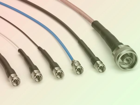
Micro coaxial cables deliver critical signals in compact electronics, from medical devices and aerospace systems to smartphones and test equipment. Their tiny size belies their complexity and vulnerability. Installation errors are common and can lead to signal degradation, intermittent connections, or complete failure – often resulting in expensive rework and downtime. Avoiding these frequent pitfalls is essential for reliable performance:
1. Mishandling the Cable (Physical Damage)
- Bending Beyond Specs: Exceeding the minimum bend radius is the #1 cause of damage. Sharp kinks permanently crush the dielectric, distorting impedance and causing signal reflections (high VSWR) or loss.
- Pinching or Crushing: Routing cables under sharp chassis edges, overtightening cable ties, or trapping cables during assembly destroys the delicate inner conductor, shield, and dielectric.
- Excessive Pulling/Tension: Applying force during routing stretches or breaks the tiny inner conductor. Secure cables before applying any tension during connector mating.
- Twisting: Rotational stress during installation twists the internal structure, compromising electrical characteristics. Route gently without torsion.
2. Improper Termination & Connectorization
- Incorrect Strip Length: Removing too much jacket leaves the shield vulnerable or exposed, causing shorts or intermittent contact. Removing too little prevents proper connector seating and shield connection. Always use a precision coax stripper calibrated for the exact cable diameter.
- Poor Shield Termination: The biggest failure point. Insufficient shield strands making contact, frayed shields, contamination (flux, solder wick strands), or shields contacting the center conductor lead to noise pickup, ground loops, poor signal integrity, and unreliable connections. Ensure a clean, complete 360-degree shield bond to the connector body or ferrule.
- Center Conductor Damage: Nicking, flattening, or over-tinning the fragile center pin during stripping or soldering introduces impedance mismatches and attenuation. Use sharp, precision tools.
- Cold Solder Joints/Insufficient Solder: Particularly problematic on micro-miniature connectors. Weak mechanical bonds cause high resistance and intermittent faults. Requires fine soldering skills and appropriate magnification/lighting.
- Incorrect Crimping: Using the wrong crimp tool or die set for the connector/cable combination, or applying insufficient/uneven force, creates unreliable mechanical and electrical connections prone to failure.
3. Routing and Environment Errors
- Ignoring Minimum Bend Radius During Routing: Even if avoided during handling, routing the cable around tight corners or through small openings without maintaining the bend radius damages it over time. Use smooth curves and bending guides if needed.
- Running Near EMI Sources: Routing micro coax parallel to high-current AC power lines, switching power supplies, motors, or other noise sources induces interference without adequate shielding. Maintain separation or use shielded conduit.
- Abrading Against Sharp Surfaces: Chassis edges, un-filed metalwork, or even rough plastic can abrade the cable jacket over time, eventually exposing the shield or damaging conductors. Use grommets, sleeves, or adhesive-backed routing clips designed for delicate cables.
- Ignoring Environmental Factors: Exposing cables to excessive heat (near heat sinks), chemicals (solvents, cleaners), sharp temperature cycling, or constant flexing without selecting cable types rated for those conditions causes premature degradation. Select cable grade (e.g., low-smoke, high-temp) appropriately.
4. Testing and Verification Omissions
- No Visual Inspection: Skipping a thorough post-install visual check under magnification misses obvious damage, poor solder joints, misplaced shields, or contamination that will cause problems later.
- Skipping Basic Continuity/Short Checks: Not verifying continuity of the center conductor and shield individually, and checking for shorts between them and to ground, before power-up is basic but essential.
- Neglecting VSWR/TDR Testing: While basic checks pass, only Vector Network Analyzer (VNA) measurement via Time Domain Reflectometry (TDR) or VSWR sweeps can identify subtle impedance mismatches caused by kinks, crushed dielectric, poor terminations, or unterminated cable ends (“stubs”). These mismatches cause signal reflections and degrade high-frequency performance. This is crucial for RF performance.
- Not Functionally Testing Under Real Conditions: Assuming installation is perfect without testing the device or system using the cable path at its operational frequencies and power levels can miss intermittent issues triggered by vibration, temperature, or specific signals.
How to Avoid These Mistakes – Key Takeaways
- Respect the Bend Radius: This is non-negotiable. Know the spec (usually 5-10x cable diameter) and enforce it always.
- Handle with Extreme Care: Treat micro coax like fragile glass fiber. Avoid sharp kinks, crushing, twisting, and excessive pulling.
- Master Termination: Invest in the correct tools (precision strippers, calibrated crimpers, fine-tip soldering irons) and develop meticulous technique. Pay laser focus to shield integrity and center conductor condition.
- Plan Routing Carefully: Avoid EMI sources, sharp edges, pinch points, and excessive tension. Use guides and smooth curves. Plan routing before terminating.
- Test Rigorously: Never skip visual inspection, continuity/short checks, and critically, VSWR/TDR testing for RF applications. Test functionally in the intended environment.
- Use the Right Cable & Connectors: Ensure the cable specifications (impedance, frequency range, shielding, temp rating) match the application. Use connectors designed for that specific cable type.
Successfully installing micro coaxial cables demands precision, patience, and strict adherence to best practices. By understanding and actively avoiding these common pitfalls, you significantly increase reliability, reduce costly failures and rework, and ensure optimal signal performance in your critical electronic assemblies.