How to Test Micro Coaxial Cable Shielding Effectiveness: A Practical Guide - Micro Coaxial Cable factory-(FRS)
Micro Coaxial Cable factory-(FRS)
INFO
Micro coaxial cables are the unsung heroes of modern electronics, enabling clear signals in everything from smartphones and medical devices to aerospace systems and automotive sensors. But their tiny size makes their shielding effectiveness (SE) absolutely critical. Poor shielding lets electromagnetic interference (EMI) sneak in or signals leak out, causing data errors, video static, reduced range, and even device malfunction.
So, how do you ensure these miniature cables are truly protected? Testing micro coax shielding isn’t one-size-fits-all. Here’s a breakdown of effective methods:
Why Shielding Matters So Much (Especially for Micro Coax!)
Dense Environments: Modern devices pack circuits tightly, creating intense EMI “noise” pollution. Effective shielding acts like a quiet room inside a noisy factory for your signal.
Signal Sensitivity: High-frequency data (HDMI, USB 3+, high-speed digital, RF signals) used in micro coax is particularly vulnerable to tiny interference bursts.
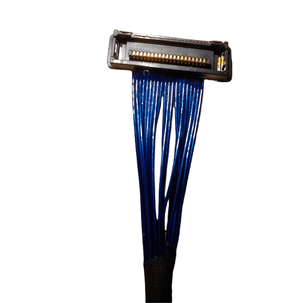
Size Constraint: Miniature size means the braid or foil shield is physically thinner and less dense, making it potentially more vulnerable than shielding on larger cables.
Regulations: Many industries (medical, automotive, aerospace, telecommunications) have strict EMI regulations. Poor shielding means non-compliance.
Common Methods to Test Micro Coaxial Cable Shielding Effectiveness
Continuity & Resistance Check (DC Resistance): The Basic Check
What it does: Measures the DC resistance of the shield itself.
How it works: Use a standard multimeter set to measure resistance (Ohms Ω). Connect one probe to the shield conductor at one end of the cable and the other probe to the shield conductor at the opposite end.
What it tells you:
Low Resistance (Usually < 0.1 Ω): Indicates good electrical connectivity of the shield along its entire length. The path exists.
High/Infinite Resistance (OL): Indicates a break in the shield braid or foil – a major defect! Shielding is compromised along the break.
Pros: Fast, easy, cheap, requires only a multimeter. Essential first step.
Cons: Only tests electrical continuity, not shielding effectiveness at relevant high frequencies. A cable with good continuity can still have poor RF shielding (e.g., loose braid).
What it does: Sends a fast electrical pulse down the cable. It measures reflections caused by impedance changes.
How it works: Connect the TDR unit to the shield and center conductor. A sharp discontinuity (like a shield break or crushed section) will cause a visible reflection spike on the TDR display at the distance of the fault.
What it tells you: Location and severity of major physical defects in the shield (or center conductor) structure, such as:
Shield conductor breaks
Significant shield crushing
Major shield deformation
Pros: Excellent for fault location along the cable length. More insightful than a simple continuity check.
Cons: Requires specialized (and often expensive) TDR equipment. Interpreting traces takes some skill. Doesn’t directly quantify SE across a frequency band. Needs access to both ends of the shield.
Tool: Time Domain Reflectometer
Vector Network Analyzer (VNA) Transfer Impedance (Zt) Measurement: The Gold Standard
What it does: Directly measures the transfer impedance (Zt) of the shield. Think of Zt as measuring “how easily” interference couples through the shield. Lower Zt = Better Shielding Effectiveness.
How it works: Requires specialized test fixtures designed for micro coaxial cables. Common types:
Triaxial/Triaxial Cell: Places the micro coax under test inside another outer conductor, injecting current between the outer conductor and the micro coax shield, and measuring voltage developed on the center conductor.
Line Injection/Longitudinal Conversion Loss (LCL): Another high-frequency method using specialized fixtures.
What it tells you: Provides a direct numerical measurement (Zt in mΩ/m) over a wide range of frequencies (MHz to GHz). This is the most accurate way to quantify shielding effectiveness for RF applications.
Pros: Direct, quantitative measure of shielding performance at the actual operating frequencies. Industry standard method.
Cons: Requires very expensive equipment (VNA), specialized/test-specific micro-coax fixtures, deep technical expertise to perform correctly, and careful calibration. Typically done in labs or by cable manufacturers.
Concept: Compare the signal received near the cable under test when an RF signal is applied to its center conductor vs. the signal received when a reference “perfect” cable is used.
How it might work: Place the cable near a sensitive RF receiver (e.g., spectrum analyzer). Inject a known signal on the center conductor. Measure signal strength “leaking” onto the receiver via poor shielding. Compare leakage between different cables.
Pros: Can reveal shielding problems without Zt equipment.
Cons: Very sensitive to test setup geometry, grounding, environment, and difficult to quantify accurately into standard SE or Zt values. Results are comparative and location-specific. Risk of environmental interference.
Practical Tips for Meaningful Testing
Start Simple: Always perform the DC continuity/resistance check first. It catches major flaws cheaply and quickly.
Test Representative Samples: Performance can vary, test samples from different production batches.
Mind the Connectors: The cable shield’s connection to its terminations (connectors) is crucial. Poor termination ruins shielding. Test cables with connectors installed when possible.
Control Variables: Keep cable routing, grounding points, and distance to receivers/transmitters consistent during comparative tests.
Environment: RF “noise” (WiFi, cell phones, power supplies) can interfere with sensitive measurements. Use shielded enclosures (like a small Faraday tent) for critical testing if possible.
Consult Spec Sheets: Reputable micro coax manufacturers perform rigorous Zt testing. Check their data sheets for shielding specifications (Zt curves are ideal) over relevant frequencies.
When Should You Test?
Validating New Designs/Samples: Before integrating a new micro coax into your product.
Troubleshooting EMI Issues: If your device experiences interference, faulty cable shielding could be the culprit.
Quality Control: Spot-checking batches from suppliers.
Comparing Different Cable Types: Choosing the best shielded cable for your application.
Conclusion
Testing micro coaxial cable shielding effectiveness is vital for reliable performance. While the Vector Network Analyzer Transfer Impedance method offers the most accurate and quantitative results, it requires significant investment. For most practical purposes:
Start with Continuity/Resistance (Multimeter) & TDR: These catch major defects and are accessible.
Rely on Manufacturer Zt Data: Source cables from reputable suppliers who provide detailed, tested shielding specifications.
Use Comparative RF Testing Cautiously: For spot checks or troubleshooting when other methods are unavailable.
The short answer is a resounding yes—coaxial cable assemblies are not only suitable for outdoor applications but have become indispensable in countless outdoor environments, from telecommunications networks to industrial facilities. The...
Coaxial cables are indispensable in a wide range of installations, including telecommunications, security systems, broadcasting, and home entertainment setups. However, the one-size-fits-all approach of standard cable lengths often fall...
In the modern landscape of medical facilities, industrial testing labs, and research centers, the demand for reliable and high-performance cable management systems has never been greater. Among the critical components in these environme...
In the rapidly evolving landscape of microwave systems, the demand for high-performance, reliable signal transmission has never been more critical. From telecommunications and aerospace to medical equipment and industrial testing, micro...
Soldering micro-coaxial cables – those tiny cables used for high-frequency signals in devices like smartphones, cameras, and RF equipment – can be intimidating. Their small size and delicate structure demand precision and the right appr...
The short answer is yes—coaxial cable assemblies can function in low-temperature environments, but their reliability and performance depend entirely on material selection, structural design, and compliance with low-temperature stan...
nternet Protocol Television (IPTV) has revolutionized how we consume media, delivering live TV, video-on-demand, and interactive content over broadband networks. While fiber-optic and Ethernet cables are often considered the gold standa...
Automotive display systems—from instrument clusters to pillar‑to‑pillar 4K/8Kpanoramic displays and HUDs—depend on high‑speed, low‑loss interconnects that survive the vehicle’s harsh environment. An automotive‑grade micro coaxial cable ...
In the modern technological landscape, sensitive equipment is everywhere, from delicate medical devices to high – tech communication gear. However, these devices are constantly under threat from Electromagnetic Interference (EMI) ...
Cable penetrations in buildings, whether for electrical, data, or communication systems, create critical vulnerabilities in fire-resistant barriers. These openings, if left unprotected, can act as pathways for fire, smoke, and toxic gas...
Micro coaxial cables are miniaturized coaxial cables distinguished by the following key features: 1. Compact Structure with Multi-Layer Shielding Micro coaxial cables consist of an inner conductor, insulation layer, shielding layer, a...
In the semiconductor industry, where device miniaturization (e.g., 3nm–5nm process nodes) and testing precision continue to advance, micro-coaxial cables have emerged as critical components in ensuring reliable signal transmission durin...
Definition and structure
An EMI shielding micro coaxial cable is a miniaturized coaxial interconnect optimized for high‑speed, high‑integrity signal paths in electrically noisy industrial environments. It comprises a central conducto...
Coaxial cable assemblies are critical in applications like telecommunications, industrial automation, and aerospace, where faulty parts can disrupt entire systems. Finding the right replacement parts requires precision—here’s a step-by-...
The race towards practical quantum computing hinges on overcoming immense technical hurdles. Among the most critical is the challenge of reliably controlling and measuring fragile quantum bits (qubits), the fundamental units of quantum ...
IntroductionQuantum computing represents the next frontier in computational power, promising breakthroughs in cryptography, material science, and optimization. However, the extreme environments required for quantum systems—specifically ...
In today’s hyper-connected world, where 5G networks transmit massive data streams, medical imaging devices capture intricate bodily details, and aerospace systems operate in extreme environments, electromagnetic interference (EMI) poses...
Micro coaxial cables (micro coax) are the unsung heroes inside countless modern gadgets. From your smartphone and laptop camera to critical medical equipment and automotive systems, these tiny cables carry vital high-frequency signals l...
Venturing beyond Earth’s protective magnetic shield means facing a relentless, invisible enemy: space radiation. For the intricate electronic systems powering satellites, rovers, and deep-space probes, this radiation isn’t j...
In the dynamic world of outdoor broadcasting, where every moment of live transmission matters, the quality and reliability of the equipment used are of utmost importance. One such crucial component is the weatherproof coaxial cable. Thi...
The demand for miniaturized, high-frequency electronics in applications like 5G, medical implants, and aerospace systems has driven the development of ultra-thin micro-coaxial conductors. However, a critical challenge in these tiny cabl...
Introduction: For mission-critical devices in medical implants, aerospace systems, industrial automation, and advanced communications, micro-coaxial cables deliver precious signals. Yet, their minute size makes them terrifyingly vu...
If you’re setting up a satellite dish, having the right wiring kit can make all the difference. A satellite dish wiring kit with premium cables isn’t just an add-on—it’s a key part of ensuring reliable signal, clear reception, and long-...
In the highly competitive coaxial cable industry, where numerous manufacturers offer similar products with comparable technical specifications, brand awareness has become a key factor in driving sales and market share. For many mid-size...
In an era where high-frequency communication and power transmission systems demand ever-increasing efficiency, the thermal management of coaxial cables has emerged as a critical challenge. Coaxial cables, widely used in 5G infrastructur...
In the relentless drive for smaller, faster, and more powerful electronics, a silent hero quietly enables success: the micro coaxial cable. These miniature marvels are far more than just tiny wires; they are the critical arteries ...
Ever looked at a blurry X-ray or a fuzzy ultrasound and worried about accurate diagnosis? In the high-stakes world of medical imaging, clarity is crucial. One unsung hero powering this precision is the micro-coaxial cable. These tiny ...
In high‑frequency electronics, medical devices, and compact RF systems, unstable impedance, signal loss, long lead times, and inconsistent quality from generic suppliers often delay launches and compromise performance. Many buyers strug...
In the intricate network of railway signaling systems, coaxial cables play a pivotal role. They are the unsung heroes that ensure seamless communication, reliable data transfer, and ultimately, the safety and efficiency of train operati...
Introduction
The oil and gas industry operates in some of Earth’s most extreme environments—from deep-sea drilling rigs to Arctic permafrost. These conditions demand connectivity solutions that combine precision, durability, and mini...
1. High-Frequency Signal Fidelity Supports Ultra-High Frequency Transmission: Micro coaxial cables can reliably transmit high-frequency signals up to 40 GHz, meeting the bandwidth requirements of high-definition audio (e.g., 24-bi...
Selecting the right micro coaxial cable manufactureris a critical decision for B2B procurement managers and design engineers. The wrong choice can lead to signal integrity issues, premature component failure, and budget overruns. This g...
You use Starlink for video calls, streaming, or staying connected off-grid. But have you ever wondered how thousands of satellites overhead work flawlessly in the brutal environment of space? One unsung hero is surprisingly sm...
Proper installation of a coaxial cable is essential to ensure optimal performance, whether it’s for your TV, internet, or other communication systems. A well-installed coaxial cable can minimize signal loss, reduce interference, a...
In the demanding arenas of defense, aerospace, and industrial applications, reliability isn’t optional – it’s mission-critical. Equipment deployed on battlefields, aboard aircraft, within satellites, or on rugged factory fl...
In high-resolution camera modules, displays, and embedded vision systems, the MIPI (Mobile Industry Processor Interface) has become the de facto standard for camera (CSI-2) and display (DSI) interconnects. As resolutions, frame rates, a...
In the dynamic world of stadiums and arenas, where thousands gather to cheer for their favorite teams or enjoy live performances, a seamless audio-visual (AV) experience is non-negotiable. From giant video screens displaying instant rep...
In the rapidly evolving landscape of medical diagnostics, precision, reliability, and miniaturization have become the cornerstones of technological advancement. Among the countless components that power cutting-edge diagnostic equipment...
The global shift toward smart infrastructure—encompassing smart grids, intelligent transportation systems, smart buildings, and industrial IoT (IIoT)—has intensified the demand for high-performance connectivity solutions. Among these, m...
Fundamentals of Bend Radius in Micro-Coaxial CablesA. Definition of Bend RadiusThe minimum bend radius (MBR) is the smallest allowable curvature a cable can withstand without permanent deformation or electrical performance degrad...
Overview of I-PEX Micro Coaxial Cable Connectors
I-PEX is a global leader in micro coaxial cable solutions, specializing in high-performance IPEX micro coax connectors and micro coaxial cable assemblies. These products are designed for.
IntroductionThe High-Temperature Resistant Micro-Coaxial Cable is a cutting-edge connectivity solution engineered to deliver exceptional performance in extreme thermal environments. Combining precision engineering with advanced mate.
Contact Us Micro Coaxial Cable factory-(FRS).
Feel free to reach out to us for any inquiries or orders