
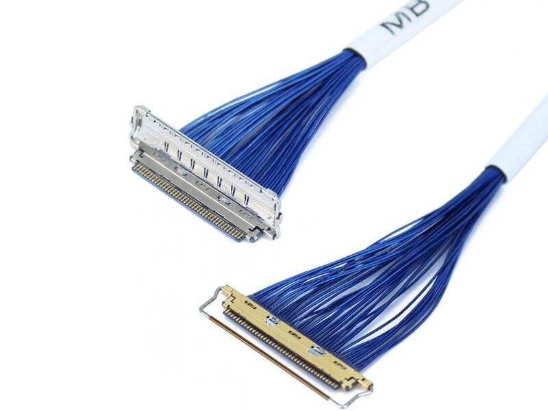
Micro Coaxial Cable factory-(FRS)
Coaxial cable assemblies (CCAs) are critical in industries like telecommunications, aerospace, and industrial automation, where they must withstand physical stress, harsh environments, and long-term use. Durability testing ensures CCAs maintain structural integrity and electrical performance over time—avoiding costly failures in applications like 5G base stations or medical equipment. Below is a step-by-step guide to rigorous, practical durability testing.
Mechanical stress (bending, twisting, pulling) is one of the most common causes of CCA failure. Tests in this category simulate real-world handling and installation conditions.
Purpose: Verify resistance to repeated bending (e.g., during cable routing or equipment movement).
Standards: Follow IEC 60794-1-2 (for fiber-optic coaxial hybrids) or UL 444 (for general CCAs).
Procedure:
Pass Criteria: No visible cracks in the jacket, no conductor breakage, and electrical parameters (see Section 3) change by ≤5%.
Purpose: Evaluate resistance to twisting (e.g., during installation in tight spaces).
Procedure:
Pass Criteria: No jacket separation, no shield fraying, and impedance variation ≤3Ω.
Purpose: Ensure the assembly withstands pulling forces (e.g., accidental tugging or weight loading).
Procedure:
Pass Criteria: No detachment of connectors from the cable, no conductor stretching beyond 1% of original length.
CCAs often operate in extreme temperatures, humidity, or corrosive environments. These tests validate performance under such stress.
Purpose: Simulate temperature fluctuations (e.g., outdoor CCAs exposed to day-night changes or aerospace conditions).
Standards: Refer to MIL-STD-810H (military-grade) or IEC 60068-2-14.
Procedure:
Pass Criteria: No jacket hardening/cracking, no electrical performance degradation (see Section 3).
Purpose: Test resistance to moisture (e.g., CCAs in marine or tropical environments).
Procedure:
Pass Criteria: No moisture inside the assembly, and electrical loss (insertion loss) increases by ≤0.5 dB.
Purpose: Evaluate corrosion resistance (e.g., coastal or industrial CCAs exposed to salt-laden air).
Procedure:
Pass Criteria: No rust on connectors (e.g., brass or stainless-steel parts), no shield corrosion, and electrical continuity remains intact.
Durability is not just physical—CCAs must maintain consistent electrical performance (e.g., signal transmission) after stress. Key tests include:
Purpose: Ensure the CCA’s characteristic impedance (e.g., 50Ω or 75Ω) stays within specs (critical for signal integrity).
Procedure: Use a vector network analyzer (VNA) to measure impedance at 100 MHz–6 GHz (common for high-frequency CCAs) before and after mechanical/environmental tests.
Pass Criteria: Impedance variation ≤5% of the rated value (e.g., 50Ω CCAs must stay between 47.5Ω and 52.5Ω).
Purpose: IL measures signal loss through the CCA; RL measures signal reflection (both critical for low-noise transmission).
Procedure:
Pass Criteria: IL increases by ≤0.1 dB/m; RL decreases by ≤3 dB.
Purpose: Confirm no conductor breaks or connector failures.
Procedure: Use a multimeter to check continuity between the center conductor and connector pins, and between the shield and connector shells.
Pass Criteria: Zero resistance (full continuity) in all paths.
To ensure reliable results, follow these best practices:
Durability testing of coaxial cable assemblies requires a holistic approach, combining mechanical, environmental, and electrical evaluations to mimic real-world use. By following the methods outlined above—from 10,000-cycle bending tests to salt spray exposure—you can validate a CCA’s long-term reliability.
For manufacturers and buyers seeking CCAs that meet these rigorous durability standards, FRS brand factory is a trusted partner. FRS integrates all the testing protocols detailed here into its production process: every CCA undergoes 10,000-cycle bending tests, 50 temperature cycles (-40°C to 85°C), and full electrical performance checks (impedance, IL, RL) using calibrated VNA equipment. With a dedicated team of engineers monitoring each test step and adherence to MIL-STD-810H and IEC standards, FRS ensures its CCAs deliver consistent durability in telecommunications, industrial, and aerospace applications. Choose FRS for coaxial cable assemblies you can test—and trust—for the long haul.
Our factory offers high-quality products at competitive prices

KEL’s Micro Coaxial Cable solutions are at the forefront of modern electronic connectivity, offering exceptional performance in high-speed data transmission, miniaturization, and reliability. These connectors are integral to various.
In LVDS (Low Voltage Differential Signaling) display systems, Micro-coaxial Cable (also referred to as Micro Coax Cable) stands out as an optimal solution for high-resolution, high-reliability signal transmission. Designed to meet the str.
Feel free to reach out to us for any inquiries or orders