
Micro Coaxial Cable factory-(FRS)
Coaxial cable assemblies are widely used in telecommunications, broadcast, and industrial applications for their ability to transmit high-frequency signals with minimal interference. However, poor signal quality—such as signal loss, noise, or intermittent drops—can disrupt operations and degrade performance. Troubleshooting these issues requires a systematic approach to identify root causes and implement effective solutions. Below is a step-by-step guide to resolve poor signal problems in coaxial cable assemblies.
Before starting physical inspections or tests, gather the necessary tools and information to ensure efficiency: Essential Tools: Signal generator, power meter, network analyzer (for impedance checking), multimeter, cable cutter, crimping tool, and replacement connectors (e.g., F-type, BNC).System Documentation: Schematic diagrams of the cable route, signal specifications (frequency range, expected power levels), and installation records (e.g., cable type, length, connector model).Safety Precautions: Disconnect power from the system to avoid electrical hazards, especially when working with active components like amplifiers.
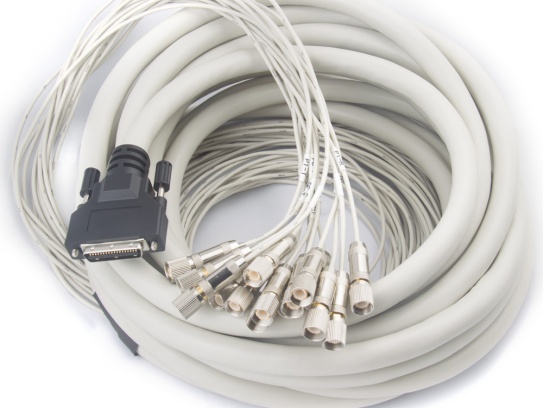
Physical defects are the most common cause of signal degradation. Carefully examine the entire cable assembly: Cable Jacket: Look for cuts, abrasions, or bulges. A damaged jacket can expose the inner shielding to moisture, dust, or physical stress, leading to signal leakage.Connectors: Check for bent pins, corrosion, or loose fittings. Corroded connectors (often caused by humidity) increase contact resistance, while bent pins can disrupt signal continuity.Shielding Layer: Ensure the braided or foil shielding is intact and properly grounded. A broken shield allows external electromagnetic interference (EMI) to enter the cable.Cable Bends: Avoid sharp bends (typically more than 10x the cable diameter). Excessive bending crushes the dielectric material, altering impedance and causing signal reflection.
Loose or improper terminations are a frequent culprit. Follow these steps: Disconnect the cable from both ends and reattach connectors firmly, ensuring a snug fit without over-tightening (which can damage threads).Verify that connectors are crimped or soldered correctly. For crimped connectors, use a torque wrench to meet the manufacturer’s specifications (usually 8–12 in-lbs for F-type connectors).Inspect the center conductor: it should be straight, not frayed, and properly aligned with the connector’s pin.
Use a signal generator and power meter to measure signal performance: Connect the signal generator to one end of the cable and set it to the system’s operating frequency (e.g., 1 GHz for cable TV).Place the power meter at the other end and record the received signal power. Compare it to the expected loss (coaxial cables typically have 2–5 dB loss per 100 feet at 1 GHz, depending on the cable gauge).If loss exceeds specifications, the cable may be damaged, too long, or of the wrong type (e.g., using RG-59 instead of low-loss RG-6 for high-frequency applications).
Impedance mismatch (most coaxial systems use 50Ω or 75Ω) causes signal reflection and loss. Use a network analyzer to check: Connect the analyzer to the cable and perform a return loss test. A return loss of -15 dB or lower indicates good impedance matching; values higher than -10 dB mean significant reflection.Common causes of mismatch include damaged dielectric material, incorrect connector installation, or mixing cables of different impedances.
External EMI or cross-talk can corrupt signals: Check if the cable runs near power lines, motors, or other high-frequency devices. Move the cable away from these sources or use a shielded coaxial cable with a higher braid coverage (e.g., 95% vs. 60%).For multi-cable setups, ensure cables are not bundled too tightly, as this can cause cross-talk between adjacent cables.
Once the issue is identified, implement repairs and re-test: Replace Damaged Components: Cut out damaged cable sections and reterminate with new connectors. Use high-quality connectors that match the cable’s impedance and frequency rating.Recheck Signal Performance: Repeat signal strength and impedance tests to confirm the problem is resolved. Ensure all values meet the system’s requirements.Document Changes: Record repairs, replacement parts, and test results for future reference.
To avoid recurring signal issues: Choose the right cable type for the application (e.g., low-loss cables for long distances, flexible cables for tight spaces).Follow proper installation guidelines, including minimum bend radius and correct connector termination.Conduct regular inspections (quarterly or semi-annually) to catch wear and tear early.
Our factory offers high-quality products at competitive prices

KEL’s Micro Coaxial Cable solutions are at the forefront of modern electronic connectivity, offering exceptional performance in high-speed data transmission, miniaturization, and reliability. These connectors are integral to various.
Meta Description: Discover our premium Flexible Micro-Coaxial Assemblies—engineered for high-frequency signal integrity, durability, and versatility in aerospace, medical, telecom, and robotics applications. What Are Flexible .
Feel free to reach out to us for any inquiries or orders