
Micro Coaxial Cable factory-(FRS)
Imagine facing a tangled nest of identical, hair-thin micro-coaxial cables during a critical system upgrade or a frantic troubleshooting session. The seconds tick by as you meticulously trace connections, hoping you don’t misplug and cause a costly failure. This frustrating scenario is all too common in complex electronic systems relying on micro-coaxial cables. Implementing custom color coding standards is the powerful, yet often overlooked, solution to transform this chaos into clarity.
Why Standard Colors Matter for Micro-Coaxial Cable Management
Micro-coaxial cables, prized for their ability to transmit high-frequency signals with excellent shielding against interference (EMI/RFI), are essential in industries like:
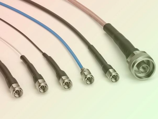
However, their small size and often uniform black exteriors make visual identification extremely difficult. This leads to:
Custom Color Coding: The Key to Taming Complexity
A generic color scheme might help a little, but customized standards designed specifically for your unique system are where the real power lies. Here’s how to design an effective system that solves real-world challenges:
1. Define Your Classification Criteria: What makes cables distinct in your application? Common categories include:
* Signal Type / Bandwidth: (e.g., RF signal in, RF signal out, Video, High-Speed Data, Low-Speed Control).
* Functional Purpose: (e.g., Power input, Sensor feed #1, Communication bus A, Redundant link).
* Voltage Level: (e.g., Main power backup, Low-voltage control, Logic level signals).
* Destination / System Section: (e.g., Module A, Module B, Control Room, Remote Antenna).
* Signal Criticality: (e.g., Safety-critical, Mission-critical, Redundant, Non-essential).
* Protocol: (e.g., USB 3.0, HDMI 2.1, SDI, LVDS).
2. Map Colors to Categories: Assign distinct, easily discernible colors.
* Select Clearly Differentiable Colors: Avoid shades too close to each other (e.g., dark red vs. dark brown). Think vibrant: Red, Blue, Green, Yellow, Orange, Purple, White, Black, Gray, Brown.
* Consider Industry Conventions (Selectively): Use red for power/primary paths or danger if it makes sense, but prioritize internal consistency over generic rules. Your system is unique.
* Prioritize High Visibility: Contrast matters, especially in low-light rack environments.
3. Incorporate Labels (The Essential Partner to Color):
* Color alone isn’t always enough. Add durable, legible labels near connectors and at strategic points along longer runs.
* Label Information: Include critical details the color represents (e.g., “Video OUT – MOD1”, “PWR – 48V”, “SENSOR_TEMP_A”, “NET-A PRIMARY”). Combine color for quick visual ID and text for absolute certainty.
* Label Material: Choose labels resistant to abrasion, heat (especially near equipment), and chemicals present in your environment. Heat-shrink tubing with pre-printed identifiers offers excellent protection and permanence.
4. Physical Implementation: Making the Standard Real
* Source Pre-Colored Cables: Many manufacturers offer micro-coax with various colored jackets. This is ideal for new builds or major upgrades.
* Use Colored Sleeving/Markers: For existing cables, easily add color using heat-shrink tubing, flexible braided sleeving (techflex), or durable, adhesive wraps/cable markers in your chosen colors. Ensure markers stay securely attached.
* Strategic Color Placement: Apply color bands or markers near both ends of the cable. For very dense areas, consider color bands periodically along the run.
5. Documentation & Communication: Cementing the Standard
* Create a Master Reference: Develop a clear, accessible document (digital or print). Include:
* The color chart showing each assigned color.
* The exact definition of what each color signifies (e.g., “Red: Main RF Input Path,” “Blue: HD Video Output”).
* Any relevant labeling conventions.
* Diagrams illustrating application in key areas (racks, panels).
* Train Your Team: Ensure everyone who interacts with the system – engineers, technicians, installers – understands the standard thoroughly. Training is non-negotiable.
* Enforce Consistency: Make adherence to the color standard part of your installation and maintenance procedures. Designate ownership.
Avoiding Common Pitfalls
Real-World Impact: More Than Just Pretty Wires
Implementing a tailored color coding standard delivers tangible, ongoing benefits:
(Example Scenario: Medical Imaging System)
A hospital struggles with technician time tracing video cables between control consoles and MRI detectors. Different shielded cables look identical. Implementing a custom standard:
Labels added to each end: “(Red) Vid-OUT-Primary”, “(Green) Vid-OUT-Redundant”. Result: Fault tracing time decreased by 40%, installation errors vanished.
Conclusion: Color Your Way to Control and Clarity
The intricate world of micro-coaxial cabling doesn’t have to be a source of frustration and inefficiency. Taking the initiative to design and implement a custom color coding standard, intelligently combined with clear labeling practices, transforms cable management from a chaotic chore into a streamlined, reliable process. By investing the time upfront to define your unique system needs, map colors effectively, document meticulously, and train comprehensively, you unlock significant gains in operational efficiency, safety, and cost control. Give your micro-coaxial cables the visual identity they deserve – your team, your timeline, and your bottom line will thank you.
Our factory offers high-quality products at competitive prices

KEL’s Micro Coaxial Cable solutions are at the forefront of modern electronic connectivity, offering exceptional performance in high-speed data transmission, miniaturization, and reliability. These connectors are integral to various.
H1: Precision Instrument Micro-Coax – Engineered for Critical Signal Integrity Meta Description: Discover Precision Instrument Micro-Coax: Miniature coaxial cable solution optimized for high-frequency signal transmissio.
Feel free to reach out to us for any inquiries or orders