Documenting micro coaxial cable test results accurately is crucial for quality control, troubleshooting, failure analysis, and ensuring reliable performance in your applications. Proper documentation creates a clear record for anyone reviewing the data now or in the future. Here’s a step-by-step guide focusing on what matters most:
Tester Name/ID: Person(s) who performed the tests.
Location: Where testing was conducted (if relevant).
Instrumentation Used: List the key test equipment (e.g., “VNA: Keysight N9918A”, “LCR Meter: Fluke PM6306”, “TDR: Tektronix DSA8300”, “Cable Tester: MultiContact CrimpStar IV”).
Cable Specification & Identification:
Manufacturer & Part Number: (e.g., “CompanyX – MCX-042-50-SS”)
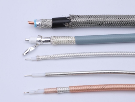
Detailed Cable Spec: Impedance (50Ω or 75Ω), core conductor material/gauge (e.g., “26AWG Silver Plated Cu”), dielectric type (e.g., “Foamed PTFE”), shield construction (e.g., “Dual Shield: Braid + Foil”), outer jacket material (e.g., “PVC”), overall diameter (e.g., “1.13mm”).
Cable Length Being Tested: Specify precisely (e.g., “1.00 meter”).
Cable Sample Identifier/Lot/Batch Number: Essential for traceability.
Connector Types: Specify the connectors on each end precisely (e.g., “End A: U.FL (IPX)”, “End B: MMCX”).
Connector Termination Quality Notes: Any observations during visual inspection before electrical testing.
Test Setup Details:
Test Configuration Sketch/Diagram: (Highly Recommended) Even a simple sketch showing:
Test equipment inputs/outputs.
Cable under test orientation.
How connectors interface to fixtures/test ports (e.g., “End A -> VNA Port 1 via SMA(f)-U.FL(m) adapter”). Include model numbers of key adapters/fixtures.
If using a reference plane or calibration type.
Calibration: Record calibration method used (e.g., “SOLT Calibration performed on VNA Ports 1 & 2 to SMA(f) interface plane prior to test”) and date of last calibration.
Test Parameters: Specific settings on the instruments:
VNA/TDR: Start/Stop Frequency, Number of Points (or Resolution), IF Bandwidth, Averaging Factor, Power Level. Especially for TDR: Pulse Rise Time, Acquisition Time.
LCR Meter: Test Frequency (e.g., “1 MHz”), Test Signal Level (e.g., “1V RMS”).
Environmental Conditions: Temperature and Humidity (if controlled or significantly deviating from standard lab conditions).
Connector Torque: If torque wrenches are used for mating connectors to test ports, note the applied torque (e.g., “U.FL mating: Finger tight only”, “SMA adapter mating: 8 in-lbs”).
Measured Test Results:
Test Specification: Clearly state the specification/standard each test relates to (e.g., “Insertion Loss < 0.8 dB @ 6 GHz per MIL-DTL-17” or “DC Resistance < 0.5 Ohms/m per Manufacturer Spec Sheet”).
Recorded Values: For each test performed:
Continuity & Shorts: “Pass” (Open between center/shield, continuity along center, shield continuity established) OR detailed description of any failure.
DC Resistance: Value measured at each conductor (Center Conductor Ω/m or Ω total; Shield Ω/m or Ω total).
Capacitance (pF/m or pF total): Measured value.
Insulation Resistance: Value measured (e.g., “> 1000 MΩ @ 500VDC”) and test voltage/duration.
Insertion Loss/Attenuation: Results at specified frequency points, especially maximum operating frequency and critical intermediate points. (e.g., “0.65 dB @ 1 GHz”, “1.05 dB @ 6 GHz”). Plotting is ideal, but tabulate key points.
Return Loss / VSWR: Results at specified frequency points. (e.g., “Return Loss: 18 dB @ 6 GHz” or “VSWR: 1.25:1 @ 6 GHz”).
Propagation Delay: Measured value (e.g., “4.85 ns/m”).
Delay Skew (if applicable): Between conductors in a multi-cable assembly.
Structural Return Loss (SRL) / Impedance Profile: Key observations from TDR trace (e.g., “Impedance average: 51.2Ω”, “Maximum deviation: ±2.5Ω”, location of any significant anomalies).
Bend Radius Test Results: Document the test radius used (per specification), number of flex cycles, Pass/Fail status with failure criteria, and any performance measurement taken after testing (e.g., “Loss after 1000 bends: +0.15dB @ 6GHz vs pre-bend”).
Conclusion & Review:
Pass/Fail Status: Clear statement: “All tests passed specifications” or “Failed: Shield DC Resistance exceeded limit – See Test #DCR-S02”.
Approvals: Space for signatures/dates of test engineer and reviewer.
Attachment Reference: If plots or detailed data files are generated, reference them clearly here (e.g., “See attached file: MCX-042-Batch_Plots.pdf”).
Formatting Tips for Clarity:
Use Tables: Organize results logically. Have separate tables for Cable Info, Test Setup, and Result Data.
Be Specific: Instead of “Connector”, write “U.FL (IPX)”. Instead of “Low Loss”, write “Insertion Loss = 0.72 dB @ 6 GHz”.
Plot Graphs: Where trends matter (like Loss/RL vs. Frequency), graphs are essential. Ensure axes are clearly labeled. Save plots as images or PDFs linked to the report.
Notes Section: Add a section for any relevant observations not captured elsewhere (e.g., “Minor shield fraying noted at End A during connector visual – did not affect electrical results”).
Electronic & Physical Copies: Store securely. Ensure digital filenames are descriptive and include date/lot number.
Sample Results Table Snippet:
Test Parameter
Specification
Measured Value
Unit
Frequency (if app.)
Result
Notes
Cable ID
MCX-042-50-SS-Lot#123A
Length: 1.00m, Conn: UFL-MMCX
Continuity
Open: CC-Shield Cont: CC, Shield
Pass
Pass
Visual: No damage
DC R – Center Cond.
< 0.20 Ω/m
0.18
Ω/m
Pass
DC R – Braid Shield
< 0.05 Ω/m
0.042
Ω/m
Pass
Insertion Loss
≤ 0.80 dB @ 6GHz
0.72
dB
6.0 GHz
Pass
Fig. 1
Return Loss
≥ 18 dB @ 6GHz
19.5
dB
6.0 GHz
Pass
Fig. 1
Bend Radius Test
10x Cable OD, 1000 cycles
Pass
Loss Δ @6GHz: +0.10dB
(Add more rows as needed)
Common Mistakes to Avoid:
Missing Traceability: No cable part number, lot number, or unique sample ID.
Unclear Test Setup: Not documenting adapters, calibration reference plane, or torque makes replication impossible.
Reporting Only “Pass/Fail”: Losing the actual measured values provides no detail for future analysis or trend spotting.
Vague Results: Reporting “Insertion Loss: Good” instead of specific values at specific frequencies.
Missing Frequency Points: Not reporting loss/RL at the cable’s maximum specified operating frequency.
Ignoring Visuals: Failing to document pre-existing physical damage can lead to incorrect failure attribution later.
Ignoring Test Conditions: Not recording temperature/humidity or specific instrument settings can make data hard to interpret or compare later.
No Summary/Conclusion: Forcing the reader to hunt through all data to determine if the cable passed overall requirements.
Disorganized Presentation: Scatter information, making the report hard to follow.
Coaxial cable assemblies are widely used in telecommunications, broadcast, and industrial applications for their ability to transmit high-frequency signals with minimal interference. However, poor signal quality—such as signal loss, noi...
A newly released industry report, compiled by leading market research firm Global Connect Insights, has shed light on the key factors driving competitiveness in the coaxial cable sector. Among the findings, our company’s coaxial cable p...
Meta Description: Fix your micro coax problems! Learn how to resolve VSWR spikes, solder fractures, and shield corrosion.
Article Content:Common Failures & Solutions
High VSWR at 20GHz:Cause: Improper SMA connector so...
Industrial grade micro coaxial cable is an ultra‑thin, high‑performance RF interconnect built for demanding applications that require precise impedance control, high‑density routing, and long‑term reliability under mechanical and enviro...
The answer is yes—coaxial cable assemblies are indispensable components in industrial robots, playing a critical role in ensuring stable, high-precision signal transmission that directly impacts the robots’ performance, accuracy, a...
AbstractSignal interference remains a critical challenge in high-frequency applications using micro-coaxial cables, impacting performance in 5G devices, medical imaging systems, and aerospace electronics.
IntroductionMicro-coaxia...
In the intricate world of modern electronics, where signals zip around at lightning speeds, the humble cable plays a starring role. Especially critical are micro-coaxial cables – those thin, often overlooked wires connecting every...
Product overview and where it’s used
The Hirose DF36is a 0.4 mm pitch, vertical-matingmicro-coaxial cable connector family built for ultra-compact, high-density interconnections. It is widely adopted in smartphones and mobile device...
In the intricate web of wireless communication systems, coaxial cable assemblies serve as the critical lifeline, bridging transmitters, receivers, antennas, and other key components. Their role in ensuring reliable signal transmission—f...
Coaxial cables, a staple of wired communication since the 1930s, continue to thrive in modern technology despite competition from fiber optics and wireless solutions. Their unique design—combining high bandwidth, durability, and electro...
Coaxial cable assemblies are critical components in various industries such as telecommunications, aerospace, medical equipment, and industrial automation. Their performance relies not only on high-quality materials and precise manufact...
The answer to whether coaxial cable assemblies can be used in home theater systems is a resounding “yes.” In fact, coaxial cable assemblies have long been a reliable and practical choice for various connections within home t...
Why VR headsets need low loss micro coaxial cable
High‑resolution, high‑frame‑rate VR depends on moving massive amounts of image data across very short, highly constrained interconnects inside the headset. Traditional FPC/FFC or roun...
Introduction
Micro-coaxial cables are essential for transmitting high-frequency signals in compact spaces, but harsh environments with constant vibrations (e.g., aerospace, automotive, or industrial machinery) demand specialized desi...
Coaxial cable assemblies are critical components in industries like telecommunications, aerospace, medical equipment, and industrial automation—their performance directly impacts the stability and reliability of entire systems. Finding ...
Military applications demand electronic components that can withstand extreme conditions while maintaining uncompromised performance—coaxial cable assemblies are no exception. These critical components serve as the backbone of communica...
Micro coaxial cables are the unsung heroes powering our smallest, most advanced electronics – from life-saving medical implants to cutting-edge aerospace systems and the latest smartphones. But their tiny size and delicate construction ...
Coaxial cable assemblies are critical for signal transmission in industries like telecommunications, aerospace, medical equipment, and industrial automation. Over time, wear, environmental damage, or poor maintenance can degrade their p...
Your car’s “eyes” – the ADAS cameras – are only as good as the signals they send to the brain (the control unit). Imagine your smart cruise control not seeing a stopped car ahead because the camera feed was blurry or d...
nternet Protocol Television (IPTV) has revolutionized how we consume media, delivering live TV, video-on-demand, and interactive content over broadband networks. While fiber-optic and Ethernet cables are often considered the gold standa...
You push your gaming console hard. Demanding games, fast frame rates, stunning visuals – it all demands immense power, delivered with extreme precision. Hidden deep within your PlayStation, Xbox, or other advanced console lies the unsun...
In today’s fast-paced business world, communication infrastructure is the backbone of operations—but rising costs from signal loss, frequent maintenance, and complex installations often weigh on budgets. For enterprises, broadband provi...
Last week, a highly anticipated online Q&A session on coaxial cables was successfully held, attracting hundreds of industry professionals, DIY enthusiasts, and individuals seeking to upgrade their home networks. The session featured...
In the world of telecommunications, broadcasting, and security systems, coaxial cables have long been the backbone of reliable signal transmission. However, one persistent challenge has plagued professionals in these industries for deca...
As the telecom industry marches toward 6G—targeting terabit-per-second data rates, sub-millisecond latency, and 100x higher connection density than 5G—every component in the network ecosystem faces unprecedented demands. Among these, mi...
Recently, our factory’s high-performance coaxial cable has officially clinched the Green Product Award, a distinguished honor presented by the International Green Technology & Sustainability Council (IGTSC) following a strict t...
Coaxial cable connectors and adapters play a crucial role in ensuring seamless integration of various electronic systems. Whether you’re setting up a home entertainment system, a professional audio – visual setup, or a telec...
Our factory’s coaxial cable R&D team has recently clinched a prestigious industry award, a well-deserved recognition of their relentless efforts and outstanding innovations in the field.
The award, presented by a leading au...
Micro-coaxial cables are the unsung heroes of our connected world. Packed into everything from cutting-edge smartphones and laptops to life-saving medical devices and high-frequency aerospace systems, they carry vital signals that power...
In the dynamic world of modern manufacturing, multi-robot assembly lines represent the pinnacle of efficiency, speed, and precision. These complex systems, where multiple robotic arms collaborate seamlessly, demand flawless communicatio...
In the complex and varied operating environments of modern industries, the performance and durability of coaxial cables are subjected to severe challenges. From extreme temperatures to high humidity, from violent vibrations to corrosive...
In the complex and ever – changing landscape of modern industry, coaxial cables serve as the vital lifelines of communication and signal transmission. Whether in the harsh offshore oil platforms, the humid and hot chemical plants,...
Conductors: The Core of Signal TransmissionThe inner conductor is responsible for carrying electrical signals. Material choices prioritize conductivity, flexibility, and resistance to skin effect (signal loss at high frequencies).
...
In the realm of CCTV and security camera systems, reliable signal transmission is the backbone of effective surveillance. Among the various cabling options available, coaxial cable has long stood as a trusted choice, renowned for its ab...
In military operations, reliable communication can make the difference between mission success and failure. Military-grade communication systems demand components that can withstand extreme conditions while delivering consistent perform...
For ham radio operators and amateur communicators, the coaxial cable is far more than a “connecting wire”—it is the lifeline of signal integrity. A poorly chosen or installed coaxial cable can lead to significant signal loss...
Implantable medical devices (IMDs) represent a revolution in healthcare, restoring function, monitoring vital signs, and saving lives. From pacemakers and neurostimulators to cochlear implants and advanced biosensors, these devices rely...
In the realm of wireless communication, wireless base stations serve as the vital hubs connecting devices to networks. And among the key components ensuring their smooth operation, coaxial cables play an indispensable role. This article...
Modern trains are marvels of engineering, relying on complex electronic systems for safe and efficient operation. At the heart of these systems – controlling everything from signaling and automatic train protection (ATP) to door control...
Meta Description: Discover premium RF micro coaxial cables engineered for high-frequency signal transmission in compact devices. Explore specs, applications, and benefits for telecom, medical, and aerospace industries.
.
In LVDS (Low Voltage Differential Signaling) display systems, Micro-coaxial Cable (also referred to as Micro Coax Cable) stands out as an optimal solution for high-resolution, high-reliability signal transmission. Designed to meet the str.
Contact Us Micro Coaxial Cable factory-(FRS).
Feel free to reach out to us for any inquiries or orders