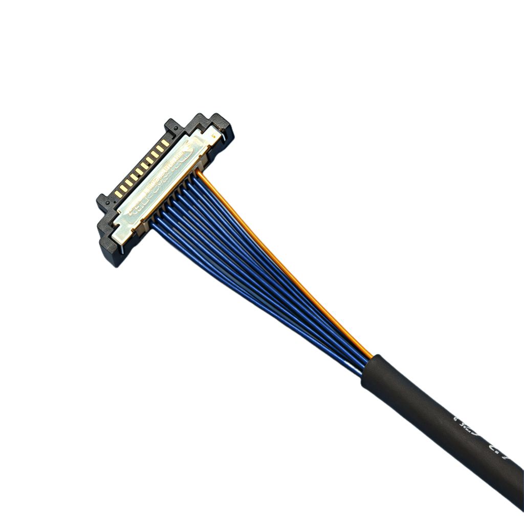
Micro-coaxial cables (“micro-coax”) are the unsung heroes of modern electronics, carrying high-frequency signals critical for everything from 5G phones and medical devices to drones and high-speed data links. But their tiny size (often less than 1mm!) makes termination – attaching the connector – a delicate and precise operation. Get it wrong, and you invite signal loss, reflections, intermittent connections, or complete failure. Get it right, and you ensure reliable, high-performance signal integrity. This guide breaks down the essential steps and best practices.
Why Proper Termination is Non-Negotiable
Micro-coax operates at high frequencies where even minor imperfections wreak havoc:
Impedance Mismatch: Incorrect stripping or connector seating alters the cable’s characteristic impedance (usually 50 or 75 ohms). This causes signal reflections, distorting the waveform and degrading data integrity.
Signal Loss (Insertion Loss): Poor solder joints, damaged conductors, or dielectric compression increase resistance, literally sucking the strength out of your signal.
Return Loss (VSWR): Reflections caused by mismatches mean less power reaches its destination and more bounces back, potentially damaging sensitive components.
Intermittency & Failure: Cold solder joints, broken center conductors (especially fragile stranded types), or shorts lead to unreliable connections that fail under vibration or temperature changes.
Essential Tools & Materials
Gather these before you start:
High-Quality Micro-Coax Connectors: Match the cable diameter and impedance exactly (e.g., 0.81mm, 50-ohm). Common types: MMCX, SMP, SMPM, GPPO, miniature SMA variants. Never guess – use the manufacturer’s recommended part.
Precision Stripping Tool:Crucial! Dedicated micro-coax strippers (e.g., from I-PEX, JFW, or Paladin) with depth-controlled blades for the specific cable diameter are ideal. Generic strippers often cause damage.
Magnification: A high-quality stereo microscope (10x-20x) or high-magnification visor is mandatory for inspecting work.
Fine-Tip Soldering Iron: Temperature-controlled (typically 600-700°F / 315-370°C), ESD-safe, with a very fine conical or chisel tip (0.5mm – 1mm). Use lead-free solder appropriate for RF (e.g., SnAgCu) or high-reliability SnPb if permitted.
Flux: Rosin-core solder usually suffices, but liquid no-clean flux applied sparingly with a toothpick can help tricky joints. Avoid acid-core flux!
ESD Protection: Wrist strap and mat to prevent static damage to sensitive components.
Fine Tweezers: Non-magnetic, anti-static.
Deionized (DI) Water & Isopropyl Alcohol (IPA): For cleaning flux residue after soldering.
Lint-Free Wipes: Kimwipes or similar.
Cable Prep Board (Optional but Recommended): Secures the tiny cable during stripping and soldering.
Vector Network Analyzer (VNA) or TDR (Optional but Ideal): For verifying electrical performance (Return Loss, VSWR).
Step-by-Step Termination Process (General Guide – ALWAYS consult your specific connector datasheet!)
Preparation is Paramount:
Clean Workspace: Ensure it’s well-lit, ESD-safe, and free of debris.
Measure Twice, Cut Once: Determine the exact length needed, adding a small margin for termination. Cut cleanly and squarely using sharp wire cutters.
Identify Layers: Know your cable’s construction (center conductor diameter, dielectric diameter, braid/shield type, jacket diameter).
Precision Stripping (The Most Critical Step):
Secure the Cable: Use a prep board or gentle vise to hold the cable end perfectly still.
Set Stripper Depths:Meticulously adjust your micro-coax stripper using the connector manufacturer’s specifications. This defines the lengths of exposed center conductor and dielectric.
Strip the Jacket: Make a clean, circumferential cut only through the outer jacket. Remove the jacket piece carefully.
Fold Back the Braid/Shield: Gently fold the exposed braid/shield back over the jacket. Avoid kinking or breaking strands. Some connectors require trimming this to a specific length later.
Strip the Dielectric: Make a perfectly controlled cut only through the dielectric down to, but not nicking, the center conductor. Remove the dielectric sleeve cleanly. Any nick or gouge in the center conductor significantly weakens it and harms performance.
Inspect Under Magnification: Check for:
Undamaged, perfectly round center conductor.
Cleanly cut dielectric edge (no fraying or melting).
Undamaged, neatly folded braid/shield.
No stray shield strands touching the center conductor.
Connector Assembly & Soldering:
Dry Fit: Assemble the connector parts onto the stripped cable without solder to ensure everything fits correctly and seats fully. Note the position.
Center Conductor Soldering:
Insert the exposed center conductor fully into the connector pin’s receptacle.
Apply the tiniest amount of flux if needed (often the rosin core is sufficient).
Touch & Go Soldering: Briefly touch the side of the connector pin (not directly on the fragile center conductor) with the pre-tinned soldering iron tip, then feed a minuscule amount of solder (1-2mm) into the joint. The solder should flow smoothly around the joint via capillary action. Avoid excessive heat or solder! Overheating melts the dielectric; excess solder causes blobs and impedance issues. Remove heat immediately after flow.
Shield/Braid Termination:
Depending on the connector, this might involve soldering the folded-back braid to a connector body collar, or clamping it mechanically.
If soldering: Trim braid if necessary per datasheet. Apply flux sparingly to the braid and connector contact area. Use the iron to heat the connector body (not the braid directly) and flow solder onto the joint. Ensure a solid 360-degree connection without solder wicking up the braid under the jacket.
If clamping: Follow the connector’s assembly instructions precisely for crimping or screwing down the clamp to ensure solid electrical contact and strain relief.
Assemble Connector Body: Complete the assembly of any outer shells, nuts, or strain relief boots according to the datasheet. Ensure proper torque if specified.
Post-Assembly Cleaning & Inspection:
Clean Flux Residue: Use DI water followed by IPA and lint-free wipes to remove all flux residue. Contaminants can cause corrosion or leakage currents at high frequencies.
Thorough Visual Inspection (Under Microscope):
Center conductor: No nicks, breaks, or excessive solder.
Solder joints: Shiny, smooth, concave fillets (not dull, blobby, or convex). No cold joints or bridges.
Dielectric: No melting, charring, or compression.
Braid/Shield: Securely terminated, no loose strands near the center conductor.
Overall assembly: Connector fully seated and assembled correctly.
Testing (The Ultimate Proof):
Continuity Check: Use a multimeter to verify no short between center pin and outer shell, and good continuity along the center conductor and shield.
Electrical Performance (Highly Recommended): Connect the cable assembly to a Vector Network Analyzer (VNA) or Time Domain Reflectometer (TDR).
Return Loss / VSWR: Measures reflections due to impedance mismatches. Should meet the connector/cable specifications across the required frequency band (e.g., >15dB Return Loss is often a minimum target).
Insertion Loss: Measures signal attenuation. Compare against the cable’s specified loss per length plus connector loss specs.
A TDR can pinpoint the location of any impedance discontinuity (e.g., a bad solder joint).
Common Pitfalls & How to Avoid Them
Stripping Damage: Using the wrong tool or incorrect depth settings. Solution: Invest in a proper micro-coax stripper and calibrate meticulously.
Overheating: Applying the soldering iron too long. Solution: Use a temperature-controlled iron, fine tip, and practice the “touch and go” technique. Let joints cool between steps.
Excess Solder: Creates impedance bumps and potential shorts. Solution: Use very thin solder and feed minimally.
Ignoring Datasheets: Assuming all micro-coax/connectors are the same. Solution: Always obtain and follow the specific manufacturer’s instructions for both the cable and connector.
Overview and definition
Medical grade micro coaxial cable for ultrasound probes is a highly miniaturized, high‑density interconnect that carries high‑frequency ultrasound signals between the probe’s piezoelectric array and the imagin...
Micro coaxial cables – the tiny heroes powering high-speed signals in our electronics – are constantly evolving. As devices become more compact, powerful, and connected, these essential interconnects face new demands. Let’s explor...
Micro coaxial cables are essential in modern electronics, enabling high-frequency signal transmission in compact devices from smartphones to satellites. However, their performance and longevity are heavily influenced by temperature. Und...
In today’s digital age, coaxial cables serve as the backbone of countless critical systems—from 5G telecommunications and cable TV networks to industrial automation and medical imaging equipment. Their ability to transmit high-frequency...
Soldering micro-coaxial cables – those tiny cables used for high-frequency signals in devices like smartphones, cameras, and RF equipment – can be intimidating. Their small size and delicate structure demand precision and the right appr...
IntroductionModern electronics operate in increasingly hostile environments—factory floors with EMI from motor drives, automotive engine bays with 150°C temperatures, and satellites exposed to cosmic radiation. Micro-coaxial cables, de...
In the realm of professional cable installation, the difference between a seamless, reliable setup and a problematic, short-lived one often lies in the tools and accessories used. Whether dealing with electrical, data, coaxial, or fiber...
Micro coaxial cable is a miniaturized coaxial interconnect built to carry high‑speed, high‑frequency signals in extremely confined spaces. Each conductor is surrounded by a precise dielectric and a continuous outer shield, enabling tigh...
Coaxial cables have long been a staple in telecommunications, broadcasting, and home entertainment systems, valued for their ability to transmit high-frequency signals with minimal interference. However, one persistent challenge has bee...
Ordering bulk quantities of coaxial cable assemblies is a critical process that directly impacts project timelines, budget efficiency, and overall performance of electronic systems. Whether you’re sourcing for telecommunications, aerosp...
Micro-coaxial cables (micro-coax) – those thin, often less than 3mm diameter cables – are the unsung heroes powering critical video, RF, and data signals in drones, cameras, medical devices, and countless electronics. But their delicate...
In high-speed electronics and radio frequency (RF) designs, reliably moving signals from point A to point B without distortion or loss is critical. Two common ways to achieve this are Micro Coaxial (Micro-Coax) Cables and Microst...
Choosing the right cables for your robotics project might seem minor, but it’s critical for performance, reliability, and avoiding frustrating glitches. Micro coaxial cables – those tiny, shielded wires often used for video, data,...
Tangled cables snaking behind your desk, jumbled wires under the entertainment center, or unruly cords cluttering your workshop—these are common nuisances that not only look messy but also pose tripping hazards and make maintenance a ha...
The question of whether coaxial cable assemblies can be modified after purchase is a common one among engineers, technicians, and hobbyists who work with RF (radio frequency), video, or data transmission systems. The short answer is: so...
In any setting where cables and wires are present—whether it’s a home, office, industrial facility, or outdoor environment—keeping them organized and securely routed is more than just a matter of tidiness. It’s a critical step in ensuri...
Venturing into the deep ocean is one of humanity’s greatest technological challenges. Deep-sea Remotely Operated Vehicles (ROVs) are our eyes and hands in these crushing depths, enabling scientific discovery, resource exploration,...
MRI machines are critical diagnostic tools in healthcare, relying on precision engineering to deliver accurate imaging results. At the heart of these systems are micro-coaxial cables, which transmit high-frequency signals with minimal ...
Return Loss (RL) is a critical parameter in any RF system, indicating how effectively signal power is transmitted from a source into a load (like an antenna, circuit, or another cable) versus how much is reflected back due to impedance ...
Micro coaxial cables are the tiny workhorses powering signals in countless devices: your smartphone’s camera, medical implants, drones, high-frequency test equipment, and complex aerospace systems. Choosing reliable micro coax is ...
In the operating rooms of today, surgical robots have redefined the boundaries of precision and minimally invasive care—navigating tortuous vascular pathways, performing millimeter-scale tissue resections, and transmitting real-time 4K ...
If you’re working with RF (radio frequency) systems, antennas, or small-scale electronics, chances are you’ve encountered RG-174 micro-coaxial cables. These thin, flexible cables are popular for their low loss and durability in tight s...
In the world of theater, sound is not just an accessory—it’s a storytelling tool that breathes life into performances. A single note from a violin, a whispered line from an actor, or the roar of a crowd in a musical number must reach ev...
We are excited to announce the release of our latest coaxial cable model, a product that embodies our commitment to innovation, quality, and meeting the evolving needs of the market.
In today’s rapidly advancing technological ...
IntroductionArctic research stations operate in one of Earth’s harshest environments, where temperatures plummet below -50°C. To maintain critical communication and data transmission, these stations rely on cold-resistant micro-coaxial ...
In an era where precision and reliability are paramount, the packaging of coaxial cables has undergone a transformative overhaul to address the challenges of modern logistics, environmental sustainability, and end-user performance. This...
The demand for micro-coaxial cables is surging, driven by high-speed data transfer in devices like smartphones, medical equipment, automotive sensors, and aerospace systems. Alongside performance, manufacturers and end-users are increas...
In the realm of utility infrastructure, underground direct burial cables stand as a critical component, offering a reliable and space-efficient alternative to overhead lines. Designed to withstand harsh environmental conditions while de...
HD video is characterized by its high resolution, vivid colors, and smooth motion. To achieve this level of quality, a large amount of data needs to be transmitted accurately from the source (such as a Blu – ray player, camera, or...
In the rapidly evolving landscape of smart lighting, where connectivity, miniaturization, and performance are paramount, micro-coaxial cables have emerged as a critical component. Unlike traditional wiring solutions, these ultra-thin, h...
In the realm of modern communication and electronic systems, coaxial cable assemblies stand as a cornerstone technology, playing a pivotal role in transmitting signals with reliability and efficiency. Among the key performance metrics t...
In the field of electronic measurement, where precision and signal integrity are paramount, micro-coaxial cables have emerged as a critical component. Unlike standard coaxial cables, these miniature versions are engineered to deliver ex...
5G carrier aggregation (CA) has emerged as a cornerstone technology to unlock the full potential of next-generation wireless networks, enabling higher bandwidth, lower latency, and seamless connectivity across diverse use cases—from urb...
In the first three quarters of 2025, our factory’s coaxial cable products have achieved record-breaking sales performance, with the total sales volume increasing by 65% compared with the same period last year and the sales revenue...
In the fast-paced world of technology, the quest for more efficient and reliable signal transmission is unending. One of the recent breakthroughs in this area comes in the form of new diamond-coated micro-coaxial cables, which have the ...
n an era defined by lightning-fast connectivity and shrinking electronic devices, micro coaxial cables have emerged as unsung heroes powering the seamless flow of data. These miniature yet mighty cables are engineered to meet the escala...
Micro-coaxial cables, the unsung heroes of our hyper-connected world, are vital for transmitting high-frequency signals in smartphones, medical devices, aerospace systems, and countless other advanced technologies. While their performan...
With the continuous advancement of communication technology, the application scenarios of coaxial cables are becoming more and more extensive, and higher requirements are put forward for their installation quality. In response to the ne...
As new consumer electronics and network devices—such as 4K/8K smart TVs, 5G CPE routers, and 4K security cameras—become increasingly prevalent, many users wonder if their existing coaxial cables or newly purchased ones can work seamless...
The relentless demand for higher bandwidth, faster data transfer, and miniaturized electronics has placed immense pressure on manufacturers of micro-coaxial cables. These tiny, high-performance cables are the critical arteries for signa...
IntroductionThe High-Temperature Resistant Micro-Coaxial Cable is a cutting-edge connectivity solution engineered to deliver exceptional performance in extreme thermal environments. Combining precision engineering with advanced mate.
Overview of I-PEX Micro Coaxial Cable Connectors
I-PEX is a global leader in micro coaxial cable solutions, specializing in high-performance IPEX micro coax connectors and micro coaxial cable assemblies. These products are designed for.
Contact Us Micro Coaxial Cable factory-(FRS).
Feel free to reach out to us for any inquiries or orders