
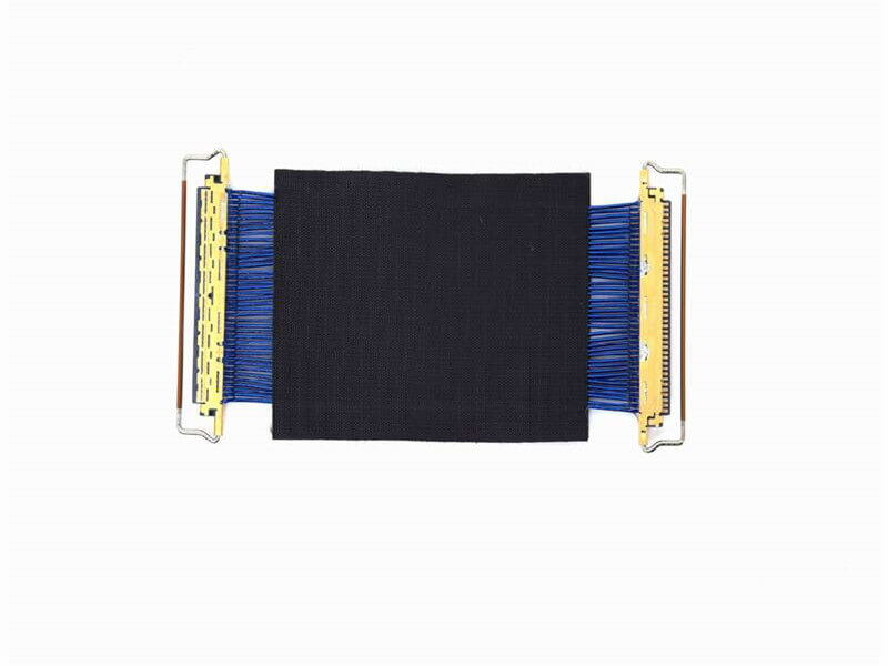
Micro Coaxial Cable factory-(FRS)
In the intricate web of wireless communication systems, coaxial cable assemblies serve as the critical lifeline, bridging transmitters, receivers, antennas, and other key components. Their role in ensuring reliable signal transmission—free from interference, loss, or degradation—directly impacts the performance, efficiency, and longevity of the entire network. Whether for 5G base stations, Wi-Fi routers, satellite links, or IoT devices, choosing the right coaxial cable assemblies is not just a technical decision but a cornerstone of operational success. This guide breaks down the essential factors to consider when selecting coaxial cable assemblies for wireless communication, ensuring your choice aligns with your system’s unique requirements.
Wireless communication operates across a vast spectrum of frequencies, from low-frequency (LF) bands used in AM radio to ultra-high-frequency (UHF) and millimeter-wave (mmWave) bands central to 5G and satellite communication. Coaxial cable assemblies are designed to perform optimally within specific frequency ranges, and selecting one that aligns with your system’s operating band is non-negotiable.
For example, 5G networks rely on both sub-6 GHz (3.5 GHz, 28 GHz) and mmWave (24–100 GHz) bands to deliver high data rates. A cable assembly rated for sub-6 GHz will struggle with signal loss at mmWave frequencies, while a mmWave-optimized cable may be overengineered (and costly) for lower bands. Similarly, Wi-Fi 6/6E operates at 2.4 GHz, 5 GHz, and 6 GHz; choosing a cable that covers these bands ensures minimal signal degradation.
Always check the manufacturer’s specifications for “frequency range” or “operating frequency.” Look for assemblies that not only cover your current band but also leave room for future upgrades—critical as wireless standards (e.g., 6G) continue to evolve.
Impedance, measured in ohms (Ω), refers to a cable’s resistance to the flow of alternating current (AC) signals. In wireless communication, impedance mismatch between the cable assembly and connected components (antennas, transceivers) causes signal reflection, where a portion of the signal bounces back instead of propagating forward. This leads to reduced efficiency, increased noise, and even damage to sensitive equipment over time.
The industry standard for most wireless communication systems is 50 Ω impedance. This value strikes a balance between power handling and signal loss, making it ideal for applications like cellular networks, radar, and satellite communication. Some legacy systems (e.g., cable TV) use 75 Ω, but 50 Ω remains the gold standard for wireless.
When selecting a coaxial cable assembly, verify that its impedance matches exactly with the impedance of your antennas, transmitters, and receivers. Even a small mismatch (e.g., 50 Ω cable with a 75 Ω antenna) can compromise performance.
Attenuation measures how much signal strength is lost as it travels through the cable, typically expressed in decibels per meter (dB/m) at a specific frequency. Lower attenuation means more of the original signal reaches its destination—a critical factor for long-distance transmissions (e.g., between a base station and its antenna) or high-frequency applications (where signals degrade faster).
Attenuation is influenced by several factors:
For example, a 5G mmWave backhaul link spanning 10 meters demands a cable with attenuation below 2 dB/m at 28 GHz to ensure the signal remains strong enough for processing. Always compare attenuation specs at your system’s operating frequency—don’t rely on generic “low loss” claims.
Power handling refers to the maximum power a cable assembly can safely carry without overheating or degrading. This is especially critical for high-power systems like cellular base stations, radar transmitters, or broadcast antennas, where transmit power can exceed 100 watts.
Power handling depends on:
Underestimating power requirements can lead to cable failure, system downtime, or safety hazards. Overestimating, however, may result in unnecessary costs—balance is key.
Wireless communication systems operate in diverse environments: from controlled indoor settings (data centers) to harsh outdoor conditions (rooftops, deserts, marine environments). A cable assembly’s ability to resist environmental stressors directly impacts its reliability.
Key environmental factors to consider:
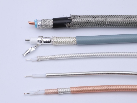
Coaxial cable assemblies are only as good as their connectors—the interface between the cable and your equipment. The wrong connector can negate all other performance gains, causing signal loss, interference, or connection failures.
Common connector types for wireless communication include:
When selecting a connector, ensure it matches your equipment’s ports and supports your frequency range. Additionally, check for features like gold plating (reduces corrosion and signal loss) and weather sealing (for outdoor use).
Wireless environments are rife with electromagnetic interference (EMI) and radio-frequency interference (RFI)—from nearby transmitters, power lines, or electronic devices. Poorly shielded cables act as antennas, picking up this interference and corrupting the signal.
Coaxial cables use layered shielding to combat this:
For sensitive applications like military communication or 5G mmWave links—where even minor interference can disrupt service—prioritize cables with high shielding efficiency (e.g., >90 dB at 1 GHz).
Installation constraints vary widely: some systems require cables to bend around tight corners (e.g., inside a router), while others need long, straight runs (e.g., between a tower and a base station). A cable’s flexibility and bend radius (the smallest radius it can bend without damage) directly affect installability and long-term performance.
Always check the minimum bend radius (both static and dynamic) to avoid kinking, which can crush conductors or damage shielding, leading to signal loss.
The performance of a coaxial cable assembly depends heavily on manufacturing quality. Poorly crimped connectors, inconsistent shielding, or subpar materials can lead to unpredictable signal loss, premature failure, or safety risks.
Look for assemblies that meet industry standards and certifications, such as:
Reputable manufacturers also provide test reports (e.g., VSWR, attenuation, and shielding effectiveness) to validate performance claims.
At FRS, we understand that the right coaxial cable assembly is the backbone of reliable wireless communication. For over [X] years, our state-of-the-art manufacturing facilities have produced assemblies engineered to excel in the factors that matter most:
Whether you’re building 5G base stations, deploying IoT networks, or designing satellite communication systems, FRS delivers coaxial cable assemblies tailored to your unique needs. Trust FRS to keep your wireless communication strong, efficient, and future-ready.
Choose FRS—where precision engineering meets uncompromising reliability.
Our factory offers high-quality products at competitive prices
Micro Coaxial Cable: High-Quality Solutions for Precision Applications Micro coaxial cables are essential components in high-performance electronic applications, providing reliable signal transmission in compact and flexible designs. A.
Meta Description: Discover premium RF micro coaxial cables engineered for high-frequency signal transmission in compact devices. Explore specs, applications, and benefits for telecom, medical, and aerospace industries. .
Feel free to reach out to us for any inquiries or orders