
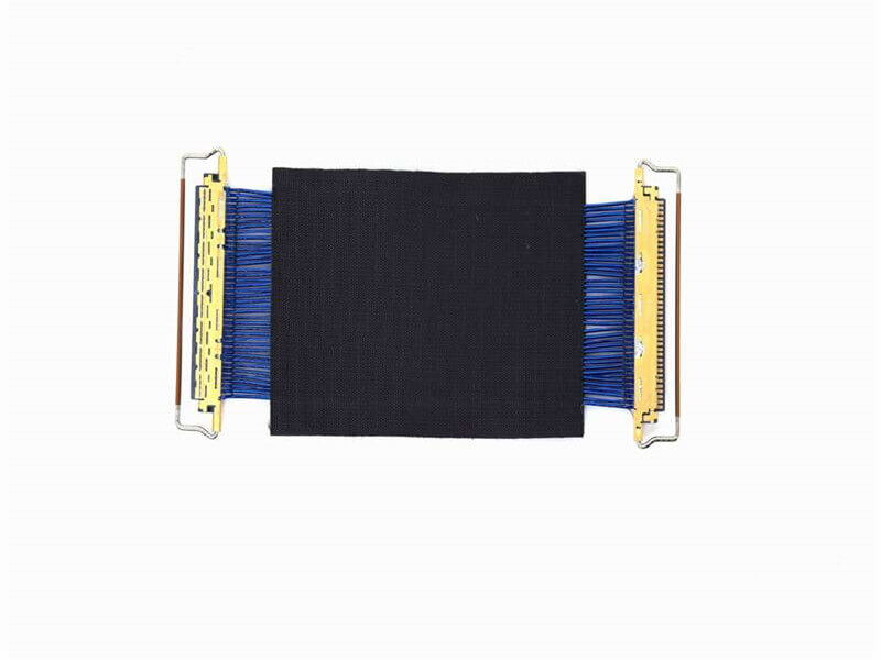
Micro Coaxial Cable factory-(FRS)
Why Bend Radius and Soldering Matter for Micro Coax Cables
Bend Radius Impact: Exceeding the minimum bend radius causes:
Signal Degradation: Increased attenuation (up to 30% at 60 GHz).
Mechanical Stress: Shield fractures and dielectric deformation.
Soldering Risks: Poor soldering leads to:
Impedance Discontinuities: VSWR >1.5, reflecting 10% of power.
Thermal Damage: Melted insulation (PTFE melts at 327°C).
Part 1: Bend Radius Guidelines for Micro Coaxial Cables
1.1 Minimum Bend Radius by Cable Diameter
Cable Diameter (mm) Static Bend Radius (Minimum) Dynamic Bend Radius (Recommended)
0.32 1.6 mm 3.2 mm
0.47 2.4 mm 4.7 mm
0.80 4.0 mm 8.0 mm
1.20 6.0 mm 12.0 mm
Source: IEC 61196-1 (RF cable bending standards).
1.2 Best Practices for Bending
Avoid Sharp Corners: Use bend radius limiters or custom fixtures.
Dynamic vs. Static Bending:
Static: Permanent bends (e.g., routing in PCBs).
Dynamic: Repeated flexing (e.g., robotic arms).
Strain Relief: Add heat-shrink tubing near connectors to distribute stress.
Part 2: Connector Soldering Techniques for Micro Coax
2.1 Tools and Materials
Soldering Iron: Temperature-controlled (300–350°C) with micro-tip (0.5–1mm).
Solder: Lead-free SAC305 (96.5% Sn, 3% Ag, 0.5% Cu) for low resistance.
Flux: Rosin-based flux (e.g., Kester 951) to prevent oxidation.
2.2 Step-by-Step Soldering Guide
Step 1: Prepare the Cable
Strip insulation with a laser stripper (0.1mm precision).
Twist the braided shield and trim the dielectric to expose 0.3mm of the center conductor.
Step 2: Tin the Conductors
Apply flux to the center conductor and shield.
Tin the center conductor with a 0.2mm solder layer.
Step 3: Solder the Connector
SMA Connector Example:
Insert the center conductor into the connector pin.
Heat the pin and apply solder until it flows evenly (2–3 seconds).
Solder the shield braid to the connector body using a circular motion.
Step 4: Inspect and Test
Microscopic Inspection: Check for cold joints or solder bridges.
Electrical Test: Measure VSWR with a VNA; ensure <1.3 at target frequency. Part 3: Common Mistakes and Solutions 3.1 Bend Radius Errors Mistake: Routing a 0.8mm cable around a 3mm corner (below 4mm static radius). Fix: Use a 3D-printed bend guide to enforce compliance. 3.2 Soldering Pitfalls Mistake: Overheating the dielectric, causing PTFE shrinkage. Fix: Use a soldering iron with auto-shutoff at 350°C. Case Study: 5G Small Cell Deployment Challenge: A 28 GHz small cell required 200+ bends in 0.47mm cables without signal loss. Solution: Designed custom jigs to maintain 4.7mm dynamic bend radius. Used laser-assisted soldering for sub-0.1dB insertion loss per connector. Result: Achieved 99.9% reliability over 12 months. SEO-Optimized FAQs Q1: What happens if I bend a micro coax beyond its minimum radius? A: Excessive bending increases attenuation (>20%) and risks shield breakage, leading to EMI interference.
Q2: Can I reuse a poorly soldered micro coax connector?
A: No. Desoldering often damages the dielectric. Replace the connector and trim the cable end.
Q3: How do I choose the right solder for 60 GHz micro coax?
A: Use high-purity Sn-Ag-Cu solder with particle sizes <25µm to minimize RF losses.
Our factory offers high-quality products at competitive prices
Micro Coaxial Cable: High-Quality Solutions for Precision Applications Micro coaxial cables are essential components in high-performance electronic applications, providing reliable signal transmission in compact and flexible designs. A.

Overview of I-PEX Micro Coaxial Cable Connectors I-PEX is a global leader in micro coaxial cable solutions, specializing in high-performance IPEX micro coax connectors and micro coaxial cable assemblies. These products are designed for.
Feel free to reach out to us for any inquiries or orders