
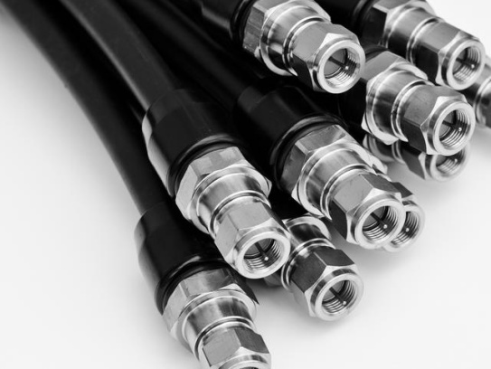
Micro Coaxial Cable factory-(FRS)
Our factory offers high-quality products at competitive prices
Meta Description: Discover the advanced features and benefits of Industrial Micro-Coaxial Wiring—engineered for precision, durability, and high-speed signal transmission in industrial environments. What is Industrial Micro-Co.
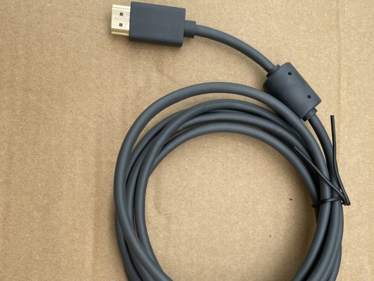
OverviewMicro-Coax for HD Video is a cutting-edge coaxial cable engineered to deliver uncompromised high-definition video quality across professional and industrial applications. Designed for reliability, precision, and versatility,.
Feel free to reach out to us for any inquiries or orders