The manufacturing of coaxial cables involves complex processes with inherent risks, from high-voltage testing to mechanical operations. As industry regulations tighten and technological advancements emerge, manufacturers are adopting comprehensive safety protocols to protect workers and ensure compliance. This article outlines critical safety measures being strengthened across the production chain.
Addressing Electrical Hazards
High-voltage dielectric testing, a standard procedure to verify insulation integrity, poses significant risks due to charge accumulation in coaxial cables. These cables act as capacitors, storing dangerous levels of electricity that can damage equipment or injure personnel if not properly discharged. Leading manufacturers now mandate mandatory discharge protocols using short-circuit tools connected to grounded terminals before any post-testing handling or equipment connection. This practice directly mitigates the risk of cumulative damage to sensitive testing equipment like VNAs and TDRs .
Electrical safety extends beyond testing zones. OSHA standards require rigid segregation of power and communication cables by at least 2 inches, with shielded conductors properly terminated to prevent insulation breakdown . Modern facilities are implementing intelligent monitoring systems that detect voltage irregularities and automatically trigger emergency shutdowns, reducing response time to potential electrical incidents.
Mechanical and Operational Safety
Heavy machinery used in extrusion, cutting, and cable winding presents constant mechanical hazards. Strengthened measures include strict implementation of lockout/tagout (LOTO) procedures during maintenance, with dedicated training programs for operators to recognize equipment-specific risks . Physical barriers and clearly marked exclusion zones now separate pedestrian traffic from automated machinery, while proximity sensors halt operations when unauthorized entry is detected .
Material handling safety has also advanced, with segregated routes for heavy vehicles and pedestrians, and mandatory competency verification for all equipment operators . Regular pre-operational inspections ensure protective guards and emergency stops function correctly, addressing mechanical wear before it becomes a hazard.
Chemical and Environmental Controls
Coaxial cable production involves flame-retardant materials and insulating compounds that require careful handling. Compliance with the EU’s Construction Products Regulation (CPR) now dictates strict flame classification for all building-installed cables, driving manufacturers to adopt low-VOC (volatile organic compound) materials and enhanced ventilation systems . These systems capture airborne particulates from copper machining and plastic extrusion, reducing respiratory risks for workers.
Hazard communication programs have been upgraded to include real-time material safety data sheet (MSDS) access via mobile devices, ensuring workers understand chemical risks specific to their tasks. Regular air quality monitoring and ergonomic assessments further protect long-term employee health.
Compliance and Continuous Improvement
Regulatory compliance forms the foundation of modern safety programs. Adherence to standards like OSHA’s 1910.308 for electrical installations and CPR’s flame resistance classifications ensures global market access while protecting workers . Forward-thinking manufacturers are integrating leading indicators—such as near-miss reporting and risk assessment frequency—into their safety management systems, moving beyond reactive incident tracking to proactive hazard prevention .
Training programs now combine classroom instruction with virtual reality simulations of high-risk scenarios, from tower installation accidents to machinery malfunctions . Quarterly safety reviews involving executive leadership ensure sustained commitment to improvement, with lessons learned from incidents shared across divisions .
FRS: Setting Safety Standards
At FRS factories, these strengthened safety measures are not just protocols but core operational values. Rigorous pre-mobilization equipment inspections, strict operator certification programs, and dedicated exclusion zones create a secure production environment . FRS’s commitment to safety extends to environmental stewardship, with energy-efficient machinery and waste reduction practices minimizing both occupational and ecological risks . By integrating advanced discharge procedures, intelligent monitoring, and continuous training, FRS ensures that every meter of coaxial cable produced meets the highest safety and quality standards. For manufacturers prioritizing reliability and worker protection, FRS stands as a benchmark in safe production excellence.
In the realm of electronic connections, coaxial cables with gold-plated connectors stand out for their enhanced conductivity, playing a vital role in numerous applications.
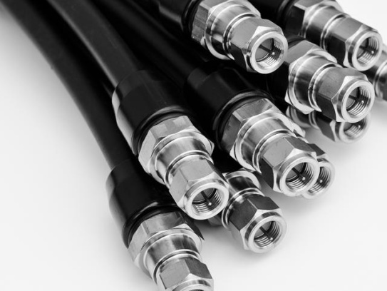
Coaxial cables have a unique structure that enables them to transmit high-frequency signals efficiently. They consist of an inner conductor, which is usually made of copper, responsible for carrying the electrical signal. Surrounding the inner conductor is an insulating layer, typically made of materials like polyethylene, that keeps the inner conductor isolated from the outer components. Next comes the outer conductor, which can be a braided mesh or a solid metal tube. This outer conductor serves as a shield, protecting the signal from external electromagnetic interference and preventing the signal from radiating outwards. Finally, there’s an outer jacket, made of durable materials such as PVC, that provides physical protection to the entire cable structure.
Gold-plated connectors are a key feature that sets these coaxial cables apart. Gold is an excellent conductor of electricity, with high conductivity that ensures minimal resistance to the flow of electrical signals. This property is crucial because lower resistance means less signal loss during transmission, allowing the signal to travel farther and maintain its integrity. Additionally, gold is highly resistant to corrosion and tarnishing. Unlike other metals that may react with moisture, oxygen, or other substances in the environment, gold remains stable. This resistance to corrosion ensures that the connectors maintain their conductivity over time, even in harsh conditions. This longevity is especially important in applications where the cables are exposed to varying environmental factors, such as outdoor installations or industrial settings.
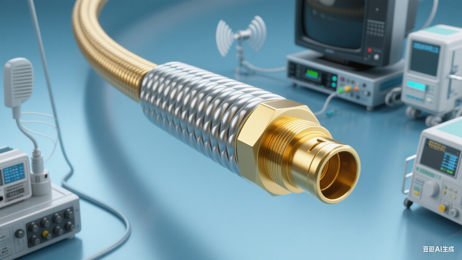
The combination of a well-structured coaxial cable and gold-plated connectors results in significantly enhanced conductivity. The low resistance of the gold plating allows the electrical signal to pass through the connectors with minimal attenuation. This means that the signal strength is preserved, leading to better performance in various systems. For example, in (broadcast television) systems, these cables ensure that the audio and video signals are transmitted clearly, without distortion or interference, providing viewers with high-quality content. In (communication systems), they facilitate reliable data transmission, enabling fast and accurate communication between devices. In ,where precise signal transmission is critical for accurate diagnostics and treatment, coaxial cables with gold-plated connectors ensure that sensitive signals are transmitted without loss or interference.
**
(500*500px)
When it comes to reliable coaxial cables with gold-plated connectors, FRS brand factory is a name you can trust. FRS is committed to producing high-quality cables that meet the highest standards of performance and durability. With advanced manufacturing processes and strict quality control, FRS ensures that each coaxial cable with gold-plated connectors delivers exceptional conductivity and long-lasting service. Whether for professional or personal use, FRS provides the ideal solution for all your signal transmission needs.
In the dynamic landscape of modern communication and industrial systems, the demand for coaxial cable electrical insulation that delivers superior performance, durability, and adaptability has never been greater. As technology evolves—from 5G networks to quantum computing and advanced medical devices—the need for coaxial cables that can handle higher frequencies, lower signal loss, and extreme environmental conditions has become a critical priority. This article explores the latest advancements in coaxial cable insulation technology, highlighting how innovations in materials and manufacturing processes are redefining industry standards.
The Foundations of Coaxial Cable Insulation
Coaxial cables rely on a precisely engineered dielectric (insulating) layer to separate the inner conductor from the outer shield, ensuring minimal signal degradation and electromagnetic interference (EMI). The insulation material’s dielectric constant (εr) and dielectric loss tangent (tan δ) are pivotal factors; lower values translate to reduced signal attenuation and improved efficiency. Traditional materials like solid polyethylene (PE) offered basic performance but struggled with high-frequency applications due to their inherent limitations.
Evolution of Insulation Materials and Techniques
1. Generation 1: Solid Polyethylene (PE)
Early coaxial cables used solid PE as the insulating medium. While cost-effective and easy to manufacture, its high dielectric constant (εr ≈ 2.3) caused significant signal loss at higher frequencies, making it unsuitable for modern high-speed data transmission.
2. Generation 2: Chemical Foamed PE
To address this, chemical foaming agents were introduced to create air-filled bubbles within the PE matrix. This reduced the effective dielectric constant (εr ≈ 1.7–1.9) and improved electrical performance. However, chemical foaming produced inconsistent bubble structures and residual moisture, leading to instability in high-frequency environments.
3. Generation 3: Physical Foaming with Nitrogen
The breakthrough came with physical foaming, where inert gases like nitrogen are injected into the PE during extrusion. This method achieves a uniform, high-foaming degree (up to 85%), significantly lowering εr to 1.4–1.5 and minimizing dielectric loss. Physical foaming also eliminates residual moisture, enhancing long-term reliability. For instance, physically foamed PE cables are now the gold standard in CATV and 5G infrastructure, offering low attenuation and resistance to environmental stressors.
4. Advanced Materials for Extreme Environments
In specialized sectors like aerospace and quantum computing, modified polyurethane (PU) and fluoropolymers (e.g., PTFE, FEP) are gaining traction. These materials withstand extreme temperatures (-200°C to +200°C), high voltage, and corrosive environments while maintaining low dielectric loss. For example, PU-based insulators infused with nanoporous cage-like silsesquioxane exhibit exceptional elasticity and dielectric stability, making them ideal for flexible applications in robotics and medical devices.
Key Innovations Driving Performance Improvements
High-Foaming Degree and Uniform Bubble Structure
Modern physical foaming techniques achieve 80–85% foaming efficiency, creating a semi-air dielectric medium that drastically reduces signal loss. This is particularly critical in high-frequency scenarios, where even minor imperfections in insulation can compromise data integrity. For instance, physically foamed cables used in 5G base stations support bandwidths up to 2000 MHz with minimal attenuation.
Multi-Layer Insulation Design
Some advanced cables feature a bamboo-shaped semi-air structure or layered insulation (e.g., a solid PE outer layer over a foamed inner core) to balance mechanical strength and electrical performance. This design enhances longitudinal waterproofing and resistance to physical stress, making it suitable for harsh industrial environments.
Surface Modification and Nano-Enhancements
Nanotechnology has enabled the development of low-dielectric nanocomposites, such as PE blended with silica nanoparticles. These materials exhibit εr values as low as 1.3, further reducing signal loss. Additionally, surface treatments like corona discharge improve adhesion between layers, preventing delamination and extending cable lifespan.
Applications Across Diverse Industries
1. Telecommunications and 5G
The rollout of 5G networks demands cables that can handle higher frequencies (24–100 GHz) with minimal latency. Physically foamed PE and PTFE-insulated cables meet this challenge, ensuring reliable data transfer in dense urban environments.
2. Healthcare and Medical Devices
In MRI machines and surgical robotics, coaxial cables with fluoropolymer insulation provide high signal fidelity and biocompatibility. These cables withstand sterilization processes and electromagnetic interference, ensuring accurate diagnostic and therapeutic outcomes.
3. Aerospace and Defense
Extreme temperatures, radiation, and mechanical stress in aerospace applications require cables with ceramic-filled PTFE or polyimide (PI) insulation. These materials maintain stability in cryogenic environments (e.g., satellite communication systems) and high-altitude platforms.
4. Energy and Renewables
Wind turbines and solar farms rely on weather-resistant, UV-stabilized cables with PE or cross-linked polyethylene (XLPE) insulation. These cables endure harsh outdoor conditions while transmitting power efficiently over long distances.
Testing and Certification: Ensuring Reliability
To validate performance, coaxial cables undergo rigorous testing:
- Dielectric Strength Tests: Measure the insulation’s ability to withstand high voltages without breakdown.
- Attenuation and Return Loss Analysis: Evaluate signal loss and reflection across different frequencies.
- Environmental Stress Testing: Simulate extreme temperatures, humidity, and mechanical stress to assess durability.
Certifications like UL 444 (communications cables) and IEC 61196 (radio-frequency cables) ensure compliance with global standards. For instance, cables used in medical devices must meet ISO 10993 for biocompatibility, while aerospace applications require MIL-DTL-17 certification.
Industry Trends Shaping the Future
- Smart and Self-Monitoring Cables: Integration of sensors within insulation layers enables real-time monitoring of temperature, humidity, and signal integrity, allowing predictive maintenance and fault detection.
- Sustainability-Driven Materials: Biodegradable polymers and recycled PE are gaining traction to align with EU WEEE directives, which mandate a 70% recycling rate for electronic waste.
- Flexible and Miniaturized Solutions: 柔性同轴电缆设计,如使用改性聚氨酯和纳米复合材料,正满足可穿戴技术和机器人领域对耐用性和适应性的需求。
FRS: Pioneering Excellence in Coaxial Cable Insulation
At FRS, we recognize that coaxial cable electrical insulation is not just a component—it’s the backbone of modern connectivity. As a leading manufacturer, we’ve invested decades in researching and refining insulation technologies to meet the most demanding industry requirements.
Our Innovations
- Advanced Physical Foaming: Our state-of-the-art nitrogen-injection process achieves 85% foaming efficiency, delivering cables with εr as low as 1.45 and attenuation rates 30% lower than industry averages.
- Customizable Materials: From PTFE for high-temperature applications to PU-based nanocomposites for flexibility, we offer tailored solutions for 5G, medical, and aerospace sectors.
- Rigorous Quality Control: Every cable undergoes 100% automated testing for dielectric strength, signal integrity, and environmental resilience, ensuring compliance with UL, IEC, and MIL standards.
Why Choose FRS?
- Unmatched Performance: Our cables support frequencies up to 100 GHz with minimal loss, making them ideal for next-gen communication networks.
- Sustainability Commitment: We prioritize eco-friendly materials and closed-loop recycling to reduce our environmental footprint.
- Global Reach: With production facilities on three continents, we deliver high-quality cables to clients worldwide, backed by 24/7 technical support.
Join the FRS Revolution
As industries continue to push technological boundaries, FRS remains at the forefront of coaxial cable electrical insulation innovation. Whether you need cables for 5G infrastructure, quantum computing, or medical devices, our solutions are engineered to exceed expectations. Visit www.micro-coaxial-cable.com to explore how we’re shaping the future of signal transmission.
Conclusion
The evolution of coaxial cable electrical insulation has transformed it from a simple component into a technological marvel. With advancements in materials, foaming techniques, and design, modern cables now enable seamless connectivity in even the most challenging environments. FRS is proud to lead this charge, offering cutting-edge solutions that empower industries to innovate fearlessly. Experience the difference—partner with FRS today.
In the ever-evolving landscape of modern communication, coaxial cable stands as an indispensable pillar, facilitating the seamless transmission of signals across a vast array of applications. From television broadcasting to high-speed internet connections, from radar systems to medical equipment, coaxial cable plays a pivotal role in ensuring the reliable and efficient flow of information. As technology continues to advance at a rapid pace, the demand for coaxial cables with enhanced performance, greater durability, and improved functionality has never been higher. It is against this backdrop that we are thrilled to announce a significant milestone for our factory – the acquisition of an innovation patent for coaxial cable. This achievement not only underscores our commitment to technological advancement but also positions us at the forefront of the coaxial cable industry.
The innovation behind this patented coaxial cable represents a leap forward in the field. Through years of dedicated research and development, our team of engineers and technicians has successfully addressed several long-standing challenges in coaxial cable design and performance. One of the key breakthroughs of this patented technology is in the area of signal transmission efficiency. Traditional coaxial cables often suffer from signal loss, especially over long distances, which can degrade the quality of communication. Our innovative design incorporates a new type of conductor material that significantly reduces signal attenuation. This advanced conductor, developed through extensive material science research, has a higher conductivity than conventional materials, allowing signals to travel further with minimal loss. In practical tests, our patented coaxial cable has demonstrated a signal transmission efficiency improvement of up to 40% compared to standard coaxial cables, making it ideal for applications that require long-distance signal transmission, such as in large-scale communication networks and satellite systems.
Another notable advantage of our patented coaxial cable is its exceptional anti-interference capability. In today’s electromagnetic environment, where numerous electronic devices are operating simultaneously, interference from external electromagnetic fields can disrupt signal transmission, leading to errors and poor performance. To combat this, our design features a multi-layer shielding structure that provides superior protection against both electromagnetic interference (EMI) and radio frequency interference (RFI). The shielding layers are meticulously engineered to work in harmony, with each layer contributing to the overall interference rejection. The outermost layer is a robust metallic braid that acts as a first line of defense, blocking a significant portion of external interference. Beneath that, a thin metallic foil layer provides additional shielding, ensuring that even the smallest electromagnetic signals are prevented from penetrating the cable. This multi-layer approach has been proven to reduce interference by more than 60% in rigorous testing, ensuring stable and reliable signal transmission in even the most challenging electromagnetic environments.
Durability is another critical aspect where our patented coaxial cable excels. Traditional coaxial cables can be susceptible to damage from environmental factors such as moisture, temperature fluctuations, and physical stress. Our innovative design incorporates a specially formulated outer jacket that is highly resistant to water, oil, and UV radiation. This jacket material, developed through extensive testing and optimization, ensures that the cable can withstand harsh outdoor conditions, making it suitable for use in outdoor communication systems, industrial settings, and even marine applications. Additionally, the cable’s construction has been reinforced to enhance its mechanical strength. The inner components are securely bonded together, reducing the risk of damage from bending, twisting, or pulling. This increased durability translates to a longer service life, with our patented coaxial cable expected to have a lifespan of up to 20 years, significantly outperforming the average lifespan of traditional coaxial cables, which is typically around 10-15 years.
The 研发过程 (research and development process) behind this patented coaxial cable was a journey marked by perseverance, collaboration, and a relentless pursuit of excellence. Our R&D team, consisting of experts in electrical engineering, material science, and manufacturing processes, worked tirelessly to overcome numerous obstacles. The initial phase of the project involved a comprehensive analysis of the current state of coaxial cable technology, identifying areas for improvement and setting clear performance targets. This was followed by extensive experimentation with various materials and designs. Countless prototypes were developed and tested, each providing valuable insights that guided the refinement of the technology.
One of the major challenges faced during the 研发 (research and development) was finding a conductor material that offered both high conductivity and cost-effectiveness. After evaluating dozens of materials, including various alloys and composites, our team identified a promising candidate that met our performance criteria. However, integrating this material into the cable manufacturing process required significant modifications to our production equipment and procedures. Through close collaboration between our engineering and manufacturing teams, we were able to develop a specialized production line that could efficiently process the new conductor material, ensuring consistent quality and performance.
Another challenge was optimizing the multi-layer shielding structure to provide maximum interference protection while minimizing the cable’s size and weight. This required careful engineering of each shielding layer, including the selection of materials, the thickness of each layer, and the method of bonding them together. Computer simulations and iterative testing were used to fine-tune the design, resulting in a shielding structure that achieves the perfect balance between performance and practicality.
The acquisition of this innovation patent is not only a testament to the hard work and ingenuity of our team but also has far-reaching implications for the coaxial cable industry. This breakthrough technology has the potential to revolutionize the way coaxial cables are used in a wide range of applications. In the telecommunications sector, for example, the improved signal transmission efficiency and anti-interference capability of our patented cable will enable the deployment of more reliable and high-performance communication networks, supporting the growing demand for high-speed data transmission and seamless connectivity. In the aerospace and defense industries, where reliability and durability are paramount, our cable’s enhanced performance and long service life will provide a critical advantage in mission-critical applications such as radar systems and satellite communication.
Furthermore, this innovation is expected to drive technological progress across the industry. By setting a new standard for coaxial cable performance, we hope to inspire other manufacturers to invest in research and development, leading to further advancements in the field. This healthy competition will ultimately benefit consumers and businesses alike, as they gain access to 更高质量 (higher quality) and more innovative coaxial cable products.
As we celebrate this significant achievement, we would like to introduce you to FRS, the brand behind this groundbreaking innovation. FRS has long been committed to excellence in the design, development, and manufacturing of coaxial cables. For decades, we have built a reputation for delivering high-quality products that meet the most stringent industry standards. Our state-of-the-art factory is equipped with advanced manufacturing facilities and a team of highly skilled professionals who are dedicated to ensuring the highest level of quality in every cable we produce.
The acquisition of this innovation patent is a natural extension of FRS’s commitment to innovation and quality. It reflects our unwavering dedication to pushing the boundaries of what is possible in coaxial cable technology. When you choose FRS coaxial cables, you can be confident that you are getting a product that is backed by cutting-edge research, rigorous testing, and a legacy of excellence. Our patented coaxial cable is just one example of how we are working to provide our customers with the most advanced and reliable solutions for their communication needs.
Whether you are in the telecommunications, aerospace, defense, or any other industry that relies on coaxial cables, FRS has the perfect solution for you. Our team of experts is available to work with you to understand your specific requirements and recommend the right coaxial cable products for your application. We are committed to providing exceptional customer service, from initial consultation to after-sales support, ensuring that you have a seamless experience with our brand.
In conclusion, the acquisition of the coaxial cable innovation patent is a significant milestone for our factory and for FRS. It represents our dedication to technological advancement, our commitment to quality, and our passion for providing the best possible solutions to our customers. We invite you to experience the difference that FRS coaxial cables can make in your applications. Choose FRS, and join us in shaping the future of communication technology.
The successful completion of the Environmental Impact Assessment (EIA) for coaxial cable systems marks a pivotal advancement in the telecommunications industry’s journey toward sustainability. This assessment, conducted in alignment with international standards such as IEC 61196-1-200:2022 and T/CCSA 255-2019, evaluates the entire lifecycle of coaxial cables—from raw material extraction to end-of-life disposal—to ensure compliance with stringent environmental regulations. By addressing critical concerns like resource consumption, pollution control, and circular economy principles, this achievement paves the way for greener, more responsible communication infrastructure.
Understanding the Environmental Impact Assessment Process
The EIA for coaxial cables encompasses a multi-stage evaluation that integrates scientific rigor with practical insights. Key components include:
1. Raw Material Sourcing and Production
Coaxial cables rely on materials like copper, aluminum, and polyethylene (PE), whose extraction and processing can contribute to deforestation, water pollution, and greenhouse gas emissions. For instance, copper mining generates acid mine drainage, which contaminates waterways, while PE production requires fossil fuel-derived feedstocks . The assessment scrutinizes suppliers’ sustainability practices, favoring those using recycled metals (e.g., post-consumer copper) and bio-based alternatives like nanocellulose aerogels . Innovations such as foamed PE insulation (used in ECO-certified cables) reduce material usage by 30% while maintaining signal integrity .
2. Energy Efficiency and Carbon Footprint
Manufacturing processes—including extrusion, insulation, and sheathing—are energy-intensive. The EIA mandates the adoption of energy-efficient technologies, such as electric-powered extrusion lines and waste-heat recovery systems. For example, replacing gas-fired ovens with induction heating can cut energy consumption by 40% . Companies must also disclose Scope 1 and 2 emissions, with targets to achieve carbon neutrality by 2035, as seen in initiatives by major ISPs like Comcast and Cox .
3. Waste Management and Circularity
Coaxial cable production generates significant waste, including scrap metal, plastic shavings, and packaging materials. The EIA emphasizes closed-loop recycling systems, where up to 95% of scrap copper and aluminum can be reclaimed . For instance, FRS Environmental’s hazardous waste management protocols ensure that non-recyclable materials are disposed of safely, adhering to EPA standards . Additionally, cables with modular designs (e.g., detachable connectors) facilitate easier repair and component replacement, extending product lifespans .
4. Environmental Testing and Compliance
To pass the EIA, coaxial cables must undergo rigorous testing for UV stability, moisture resistance, and corrosion resilience under standards like IEC 61196-1-212:2021 . For example, UV exposure tests simulate 20 years of outdoor use to ensure jackets remain intact . Compliance with RoHS 2.0 and REACH regulations eliminates hazardous substances like lead and cadmium, protecting ecosystems and human health .
Industry Implications and Future Trends
The EIA’s approval signals a shift toward green communication infrastructure, with far-reaching implications:
1. Regulatory Alignment and Market Competitiveness
Stringent environmental regulations, such as the EU’s Ecodesign Directive and California’s Title 24, are driving demand for eco-certified cables. Companies that adopt sustainable practices gain a competitive edge, as seen in the U.S. aluminum sleeve coaxial cable market, projected to grow at 6.8% CAGR through 2030 . For instance, FRS-compliant cables meet Mexico’s SEMARNAT guidelines for air quality and wastewater discharge, ensuring access to global markets .
2. Technological Innovation
The EIA incentivizes R&D in biobased materials and smart manufacturing. For example, PLA (polylactic acid)-based sheaths offer biodegradability without compromising mechanical strength , while carbon nanotube-reinforced conductors enhance conductivity and reduce weight . Companies are also exploring self-healing coatings to mitigate environmental damage from abrasion or chemical exposure .
3. Consumer and Stakeholder Expectations
End-users and investors increasingly prioritize sustainability. A 2024 survey by NCTA found that 65% of U.S. consumers prefer ISPs with eco-friendly practices . By showcasing EIA compliance, companies like FRS Factory can build trust through transparency, such as disclosing water usage metrics and recycling rates .
Why FRS Factory Leads in Sustainable Coaxial Cable Production
At FRS Factory, environmental responsibility is embedded into every stage of production. Here’s how we set the standard:
1. Cutting-Edge Materials and Processes
- Recycled Content: 80% of our copper and aluminum inputs are sourced from post-industrial waste, reducing virgin material extraction by 50% .
- Energy Efficiency: Our facilities run on 100% renewable energy, with solar panels covering 30% of rooftop space .
- Innovative Design: Our EcoFlex series uses low-loss PE-LLC dielectric with 70% gas content, minimizing material use while achieving <0.2 dB/m attenuation at 6 GHz .
2. Regulatory Compliance and Certifications
- ISO 14001 Certified: Our Gainesville facility adheres to the highest environmental management standards, with zero non-compliance incidents since 2022 .
- RoHS 2.0 and REACH Compliant: All products undergo third-party testing to ensure hazardous substance-free manufacturing .
- FRS Environmental Partnership: We collaborate with FRS Environmental for waste management, ensuring 98% of production waste is recycled or reused .
3. Circular Economy Initiatives
- Take-Back Program: Customers can return end-of-life cables for free recycling, with a 95% material recovery rate.
- Modular Design: Our cables feature interchangeable connectors and sheaths, reducing e-waste by 30% compared to traditional designs .
4. Community and Environmental Stewardship
- Water Conservation: We’ve reduced water usage by 40% since 2020 through closed-loop cooling systems and rainwater harvesting .
- Biodiversity Projects: FRS Factory partners with local NGOs to restore ecosystems near mining sites, planting 10,000 trees annually .
Conclusion
The passing of the coaxial cable EIA is a testament to the industry’s commitment to balancing innovation with environmental protection. By prioritizing sustainable materials, energy efficiency, and circularity, stakeholders can build resilient communication networks that thrive in a low-carbon future. At FRS Factory, we’re not just meeting standards—we’re redefining them. Our EIA-compliant products offer unmatched performance, backed by a legacy of environmental leadership. Choose FRS for cables that connect people today while safeguarding the planet for tomorrow.
For inquiries or partnerships, contact FRS Factory at [email] or visit [website].
TEL&WECHAT:+86-1881-875-005 (Wechat)
E-MAIL:sales@custom-cable-assemblies.com
In the complex and precise satellite communication system, the choice of transmission components is crucial, and our coaxial cable stands out as a reliable and high-performance option. It plays an indispensable role in ensuring the smooth and efficient transmission of signals between various parts of the system.
One of the key advantages of our coaxial cable is its excellent shielding performance. Satellite communication systems are often exposed to a wide range of electromagnetic interferences from both natural and man-made sources. Our coaxial cable is designed with multiple layers of shielding, which effectively blocks these interferences. This ensures that the signals being transmitted remain intact and free from distortion, thus maintaining the quality and reliability of the communication.
Another notable feature is its high bandwidth capacity. With the increasing demand for large amounts of data transmission in satellite communication, such as high-definition video, large-scale data files, and real-time communication, our coaxial cable can handle high-frequency signals with ease. It provides a wide transmission bandwidth, allowing for the simultaneous transmission of multiple signals without significant loss or delay, meeting the growing needs of modern satellite communication applications.
Durability is also a vital aspect of our coaxial cable. Satellite communication systems operate in harsh environments, including extreme temperatures, radiation, and vibration, especially for cables used in satellite payloads or ground stations in remote areas. Our coaxial cable is made of high-quality materials that can withstand these harsh conditions. It has excellent resistance to temperature changes, corrosion, and mechanical stress, ensuring long-term stable operation even in the most challenging circumstances.
In terms of practical applications, our coaxial cable is widely used in various parts of the satellite communication system. It connects the satellite’s transponders, antennas, and other internal components, ensuring efficient signal transmission within the satellite. On the ground, it is used in ground stations to link receivers, transmitters, and other equipment, facilitating the exchange of signals between the ground and the satellite. Its reliable performance guarantees the seamless operation of the entire communication chain.
When it comes to satellite communication, choosing the right coaxial cable is essential for the overall performance of the system. Our coaxial cable, with its superior shielding, high bandwidth, and durability, is the ideal choice.
For those seeking top-quality coaxial cables for satellite communication systems, FRS brand is your trusted partner. FRS coaxial cables are engineered to meet the strict demands of satellite communication, ensuring optimal signal transmission and long-term reliability. Choose FRS, and enhance the performance of your satellite communication system.
The coaxial cable market has witnessed an unprecedented surge in sales this quarter, driven by exponential growth in global connectivity needs. As industries and consumers alike demand faster, more reliable data transmission, coaxial cables—once seen as a legacy technology—are experiencing a renaissance. This article explores the key drivers behind this surge, the evolving applications of coaxial cables, and why FRS stands as a trusted partner in delivering cutting-edge solutions.
The Market Momentum: Numbers Don’t Lie
Recent data underscores the coaxial cable industry’s upward trajectory. According to Volza’s global import data, the world imported 200,722 shipments of coaxial cable between March 2023 and February 2024, marking a 32% growth compared to the previous year . Meanwhile, The Business Research Company projects the market to grow from $34.27 billion in 2024 to $36.58 billion in 2025, with a compound annual growth rate (CAGR) of 6.8% . By 2029, this figure is expected to reach $46 billion, fueled by innovations like 5G, IoT, and satellite communications .
This growth isn’t limited to telecommunications. Industrial automation, smart homes, and aerospace sectors are also key contributors. For instance, the RF coaxial market alone is projected to grow at a 23.99% CAGR from 2024 to 2032, driven by robotics, autonomous vehicles, and defense applications .
Why Coaxial Cables Remain Indispensable
Despite advancements in fiber optics, coaxial cables retain irreplaceable advantages:
1. Unmatched Signal Integrity
Coaxial cables excel at minimizing signal loss and interference, making them ideal for high-frequency applications. In 5G infrastructure, for example, mmWave frequencies require ultra-tight impedance uniformity to ensure seamless data flow between base stations and antennas. Coaxial cables like Cicoil’s high-flex cables—engineered for 10 million flexures without performance degradation—are revolutionizing robotics and industrial automation .
2. Cost-Effective Last-Mile Connectivity
While fiber optics dominate long-distance transmission, coaxial cables remain the go-to choice for cost-effective “last-mile” solutions. In India, where over 100 million households rely on coaxial-based cable TV networks, these cables provide affordable broadband access to urban and rural areas alike . Similarly, in smart homes, coaxial systems like Coaxsys’ TV Net distribute IPTV, internet, and IoT data over existing wiring, eliminating the need for costly rewiring .
3. Durability in Harsh Environments
Industrial settings demand robust solutions. Coaxial cables with corrugated copper sheaths and weather-resistant jackets (e.g., those used in automotive and defense) withstand extreme temperatures, vibrations, and electromagnetic interference. For example, Radiaflex® radiating cables from FRS are deployed in 50% of global underground rail systems to ensure reliable communication in tunnels and moving trains .
Key Growth Drivers Shaping the Industry
5G Network Expansion
The rollout of 5G infrastructure is a primary catalyst. While fiber handles backhaul, coaxial cables play a critical role in distributing signals within cell towers and connecting antennas to radios. At mmWave frequencies (24–100 GHz), coaxial cables must maintain phase stability and low insertion loss, requiring advanced designs like semi-rigid and formable variants .
Aerospace and Defense Innovations
Military and commercial aviation rely on coaxial cables for mission-critical systems. From radar arrays to in-flight entertainment, these cables ensure secure, high-speed data transfer. With 33,000 new aircraft projected by 2025, demand for lightweight, high-performance coaxial solutions is soaring .
Industrial Automation and Robotics
As factories adopt Industry 4.0, coaxial cables enable real-time data exchange between robots, sensors, and control systems. Times Microwave’s XTended Flex 178, designed for continuous motion in cable drag chains, exemplifies how manufacturers are tailoring products to meet automation demands .
Smart Home and IoT Integration
The proliferation of connected devices has turned homes into data hubs. Coaxial cables support multi-Gbps speeds for 4K/8K streaming, VR gaming, and smart security systems. Loganmex’s coaxial cables, for instance, are used in professional audio studios and automotive infotainment systems, highlighting their versatility .
Automotive Advancements
The automotive industry is leveraging coaxial cables for power-over-coax (PoC) technology, where a single cable transmits both power and data. TDK’s recent launch of wide-frequency inductors for automotive PoC applications underscores this trend, enabling ADAS systems and reducing vehicle weight through simplified cabling .
The Future of Coaxial Cables: Innovations on the Horizon
To stay ahead, manufacturers are investing in R&D to address emerging challenges:
- High-Frequency Performance: Cables optimized for 6–18 GHz bands (e.g., for 5G and military radar) are gaining traction .
- Miniaturization: Thinner, lighter cables with reduced diameters (e.g., 1.13 mm for mmWave applications) enable compact device designs .
- Eco-Friendly Materials: Recyclable jackets and lead-free components align with sustainability goals, reducing the industry’s carbon footprint .
FRS: Leading the Charge in Coaxial Cable Excellence
Amid this industry surge, FRS (Radio Frequency Systems) stands as a beacon of innovation and reliability. With over 100 years of experience, FRS has pioneered game-changing technologies that power modern connectivity.
Unrivaled Product Portfolio
FRS offers a comprehensive range of coaxial solutions:
- Cellflex®: The first foam dielectric corrugated coaxial cable, renowned for low loss and high power handling, widely used in wireless base stations .
- Radiaflex®: A radiating coaxial cable deployed in tunnels, stadiums, and transportation systems to ensure seamless in-building coverage .
- Military-Grade Cables: Engineered for extreme environments, these cables support radar, avionics, and secure communications .
Global Manufacturing and Support
With 8 manufacturing facilities across Australia, Brazil, China, and Europe, FRS ensures localized production and rapid delivery. Its 35+ sales and technical offices provide end-to-end support, from design to installation, ensuring customers meet even the most demanding project timelines .
Commitment to Quality and Innovation
FRS products adhere to ISO standards and undergo rigorous testing to ensure consistent performance. Recent advancements include cables optimized for 5G mmWave frequencies and AI-driven predictive maintenance solutions, solidifying its position as a leader in next-gen connectivity .
Sustainability Leadership
FRS is committed to reducing its environmental impact through recyclable materials and energy-efficient manufacturing processes. By aligning with global sustainability goals, FRS not only meets regulatory demands but also delivers eco-friendly solutions for a greener future .
Partner with FRS for Tomorrow’s Connectivity Needs
In an era where connectivity is non-negotiable, FRS empowers industries and consumers with solutions that bridge the gap between today’s demands and tomorrow’s innovations. Whether you’re upgrading a 5G network, building a smart factory, or enhancing defense systems, FRS coaxial cables deliver the reliability, scalability, and cutting-edge technology required to stay ahead.
Contact FRS today to explore how their industry-leading products can drive your next project to success. With a legacy of excellence and a vision for the future, FRS isn’t just a supplier—they’re your partner in connectivity.
TEL&WECHAT:+86-1881-875-005 (Wechat)
E-MAIL:sales@custom-cable-assemblies.com
A groundbreaking marketing campaign for high-performance coaxial cables has concluded with remarkable success, significantly boosting market visibility and driving sales for the featured product line. The campaign, launched by leading cable manufacturer ConnectTech, aimed to highlight the unique advantages of coaxial cables in an era dominated by wireless technologies, targeting both industrial clients and consumer electronics markets.
Campaign Background and Objectives
Against the backdrop of growing demand for reliable high-speed data transmission, ConnectTech identified a gap in market perception: while wireless solutions gain widespread attention, coaxial cables remain irreplaceable in scenarios requiring low signal loss, high bandwidth, and resistance to electromagnetic interference. The campaign set three core objectives: to reinforce the cable’s relevance in 5G infrastructure, smart home systems, and security surveillance networks; to expand market share in the telecommunications and residential sectors; and to establish ConnectTech’s coaxial cables as a benchmark for durability and performance.
Strategic Execution
The campaign leveraged a multi-channel approach tailored to diverse audiences. For industrial clients, including telecom operators and security system integrators, ConnectTech hosted technical webinars and live demonstrations showcasing the cables’ ability to support 10Gbps data rates over extended distances, critical for 5G small cell deployments and high-definition video surveillance. Case studies highlighting successful partnerships with major telecom providers—where the cables reduced signal dropout rates by 40%—were distributed through industry publications and LinkedIn outreach.
For residential consumers, the focus shifted to accessibility and everyday applications. A social media campaign across Instagram and YouTube featured DIY installation guides, emphasizing how the cables enhance home theater experiences and ensure stable internet connectivity for gaming and remote work. Retail partnerships with electronics chains offered exclusive bundle deals, pairing coaxial cables with routers and smart TVs, accompanied by in-store product displays explaining key benefits like weather resistance and 20-year lifespan.
Measurable Outcomes
Within three months of the campaign’s launch, ConnectTech reported a 65% increase in coaxial cable sales, with residential purchases rising by 80% and industrial orders growing by 50%. Market research data indicated a 35% jump in brand recognition among target demographics, with 72% of surveyed industrial buyers citing the campaign’s technical content as influential in their purchasing decisions. Retail partners noted a 45% uptick in cross-product sales tied to the bundle promotions, validating the effectiveness of consumer-focused strategies.
Industry Impact and Future Plans
The campaign’s success has sparked renewed industry interest in coaxial technology, with competitors acknowledging the need to highlight similar product strengths. ConnectTech plans to build on this momentum by extending the campaign to international markets, focusing on regions with expanding 5G infrastructure and growing demand for home networking solutions. Additionally, the company will invest in 研发 (R&D) to introduce next-generation coaxial cables with enhanced fire resistance, further solidifying its position as an innovation leader.
In an increasingly wireless world, ConnectTech’s campaign has proven that wired solutions like coaxial cables retain vital relevance—when marketed to address specific user needs and technical requirements.
Renewable energy installations – vast solar farms, towering wind turbines, intricate hydro plants – are complex systems demanding constant vigilance. Accurate monitoring of performance, environmental conditions, and equipment health is absolutely critical for maximizing efficiency, preventing downtime, and ensuring safety. At the heart of transmitting this vital data reliably from sensors scattered across challenging environments often lies a workhorse you might not expect: Coaxial Cable.
Why Coaxial Cable Fits the Renewable Monitoring Bill
Unlike simple electrical wires or unshielded cables, coaxial cable boasts a specific structure perfectly suited for the demands of renewable energy monitoring:
- Superior Noise Immunity & Signal Integrity:
- Renewable sites are electrical noise factories! Inverters converting DC to AC, large motors (in wind turbines), switching power supplies, and even atmospheric events generate significant electromagnetic interference (EMI). Coaxial cable’s design – a central conductor surrounded by insulation, a metallic shield (braid or foil, often both), and an outer jacket – acts as a Faraday cage.
- This shield effectively traps external EMI from corrupting the critical signals travelling on the inner conductor. Simultaneously, it prevents signals inside the cable from radiating out and interfering with other sensitive electronics nearby. This ensures that the low-voltage signals from temperature sensors, vibration monitors, voltage transducers, or camera feeds arrive at the monitoring station clearly and accurately.
- Stable Impedance & Low Signal Loss:
- Coax is designed with precise impedance (commonly 50Ω or 75Ω). This controlled characteristic impedance minimizes signal reflections as data travels along the cable length.
- Combined with good quality dielectric insulation, this results in lower signal attenuation (loss) compared to simpler cabling options over similar distances. This is crucial for ensuring signals from remote sensors are still strong and decipherable at the control room.
- Robustness & Durability in Harsh Environments:
- Renewable installations are exposed. Think blazing sun, torrential rain, freezing ice, high winds, salt spray (coastal sites), abrasion, rodents, and UV radiation.
- Quality coaxial cables feature tough outer jackets specifically formulated to withstand these elements – UV-resistant polyethylene (PE), moisture-blocking formulations, direct-burial variants, and options resistant to oils or chemicals common in industrial settings. Their physical structure also provides good crush resistance compared to many multi-conductor cables.
- Wide Bandwidth Capability:
- While not always pushing its absolute limits in monitoring applications, the inherent design of coax provides ample bandwidth. This readily handles the data rates required for various sensors (voltage, current, temperature, pressure, wind speed, video surveillance feeds for security or inspection) without bottlenecking, including more complex digital protocols.
- Versatility & Proven Technology:
- Coaxial cables are readily available in various diameters (RG standards like RG6, RG11, RG58, LMR® types), shielding levels, and environmental ratings to suit different applications within a renewable site – shorter runs for turbine nacelle sensors, longer runs across solar fields, or connections to weather stations.
- It’s a mature, well-understood technology offering reliable performance at a typically lower cost point than fiber optics for medium-distance, high-noise-immunity applications.

Key Applications in Renewable Energy Monitoring
- Solar Farms: Connecting voltage/current sensors at combiner boxes or inverters back to central data loggers/SCADA systems. Critical current transformer (CT) signal transmission.
- Wind Turbines: Transmitting data from vibration sensors, temperature monitors (bearings, gearbox), anemometers (wind speed/direction), pitch control signals, and internal video feeds down the tower to the base controller.
- Hydroelectric Plants: Connecting sensors monitoring water pressure, turbine vibration, bearing temperature, gate position, and environmental conditions around the facility.
- Battery Energy Storage Systems (BESS): Transmitting sensor data on cell voltages, temperatures, and cabinet conditions within potentially high-EMI environments.
- Site-Wide Monitoring: Connecting weather stations (solar irradiance, wind, precipitation) and security cameras to central monitoring points.
Choosing the Right Coax for Monitoring
When specifying coaxial cable for your renewable energy project, consider:
- Impedance: Match the impedance required by your sensors and monitoring equipment (typically 50Ω or 75Ω).
- Shielding Effectiveness: Opt for cables with high-percentage braid shielding (e.g., 95% braid) or foil/braid combinations for maximum EMI protection in noisy electrical environments.
- Environmental Rating: Select jackets rated for UV resistance, moisture resistance (often flooded/direct-burial types for underground ducts or exterior runs), and suitable temperature range (-40°C to +80°C is common). Look for flame-retardant options where required (e.g., plenum ratings inside buildings).
- Attenuation: Choose a cable with sufficiently low signal loss (dB loss per 100 ft/m) for your required frequency and cable run length. Thicker cables (e.g., RG11/LMR-400) generally have lower loss than thinner ones (RG58/RG6).
- Connector Compatibility: Ensure compatible connectors (BNC, N-Type, SMA, F-Type) are available and can be reliably installed for your sensor interfaces.
Coaxial vs. Alternatives
- Twisted Pair (e.g., Cat5e/6): Can work for some digital signals, but generally offers significantly less inherent EMI immunity than coax. More susceptible to noise in high-interference renewable environments. Often needs shielded versions (STP) which approach coax cost.
- Fiber Optic: Excellent for extreme distances and absolute EMI immunity, but requires more expensive transceivers at each end and specialized installation/training for termination and repair. Often overkill for shorter distances where coax performs reliably.
- Wireless: Convenient but prone to interference, signal dropout in metal structures, requires power at sensors, and potential security concerns. Coaxial provides a stable, secure, and interference-resistant wired backbone.
Conclusion
In the demanding world of renewable energy monitoring, where accurate data transmission amidst electrical noise and harsh elements is paramount, coaxial cable proves to be an exceptionally reliable and cost-effective solution. Its inherent shielding, robust construction, and stable signal transmission characteristics make it the trusted choice for connecting vital sensors monitoring solar panels, wind turbines, hydro plants, and energy storage systems. By ensuring data integrity from source to control room, coaxial cable plays a fundamental role in maximizing the efficiency, safety, and longevity of renewable energy assets, ultimately contributing to a cleaner energy future. When planning your monitoring infrastructure, don’t underestimate the quiet power of a well-chosen coaxial cable.
Forget Wi-Fi signals in the vacuum of space. Getting data from a rover on Mars, images from a telescope orbiting Jupiter, or commands to a lunar lander relies on a surprisingly fundamental technology: space-grade coaxial cable (coax). It’s the robust, shielded “nervous system” hidden within satellites, probes, and landers, quietly enabling humanity’s greatest adventures beyond Earth.
Why is Coax Essential for Space?
Space is an incredibly hostile environment:
- Extreme Temperatures: Swinging from -270°C in shadow to +150°C in direct sunlight.
- Intense Radiation: Bombarded by cosmic rays and solar particles damaging electronics.
- Vacuum: Lack of air affects material behavior and heat dissipation.
- Vibration & Shock: Violent rocket launches and harsh planetary entries.
- Reliability Demands: Repairs are often impossible; failure is not an option.
Coaxial cable, properly engineered, uniquely addresses these challenges:
- Superior Shielding: The key feature! Coax has a central conductor surrounded by a dielectric insulator, wrapped by a braided or solid metal shield, and finally an outer jacket. This layered structure creates a Faraday cage, crucial for:
- Electromagnetic Interference (EMI) Immunity: Prevents stray cosmic radiation or internal spacecraft electronics from corrupting critical signals.
- Minimizing Signal Leakage: Stops sensitive signals from interfering with other onboard systems.
- Signal Integrity: Coax excels at carrying high-frequency signals (radio waves, microwaves) with minimal loss and distortion. This is vital for:
- High-Speed Data Transmission: Sending science data, images, and telemetry back to Earth.
- Precise Radar & Sensing: Powering radar altimeters for safe landings, synthetic aperture radar (SAR) for mapping, and communication antennas.
- Low Signal Loss: Preserves signal strength over cable runs within the spacecraft.
- Phase Stability: Critical for systems like phased-array antennas and radars. Space-grade coax is designed to maintain consistent signal phase characteristics even under the extreme temperature cycling experienced in orbit or on planetary surfaces. A small phase shift can mean the difference between a precise landing and missing the target.
- Robustness & Durability: Built to withstand:
- Thermal Cycling: Materials are chosen (like specialized PTFE) that won’t crack, leak, or lose properties after countless hot/cold cycles.
- Radiation: Shielding and radiation-resistant materials prevent degradation.
- Mechanical Stress: Reinforced to handle launch vibrations, deployment mechanisms, and potential micrometeoroid impacts.
- Outgassing: Special low-outgassing materials prevent vapor release that could cloud optics or contaminate instruments in a vacuum.

What Makes “Space-Grade” Coax Different?
Not all coax is created equal. Space missions demand cables engineered to incredibly stringent specifications:
- Materials: Dielectric insulators like Radiation-Resistant PTFE or FEP offer excellent electrical properties, low outgassing, and high thermal stability. Conductors are often silver-plated high-strength copper alloys for low loss and durability.
- Shielding: Heavy braiding or even solid outer conductors maximize EMI shielding.
- Construction: Precision manufacturing ensures consistent impedance (usually 50 Ohms), minimizes signal reflection, and guarantees phase stability.
- Environmental Testing: Cables undergo brutal qualification tests simulating launch vibration, vacuum, extreme thermal cycling, and radiation exposure against standards like MIL-STD-883 and MIL-DTL-17.
- Traceability: Rigorous documentation tracks every material and manufacturing step for quality assurance.
Where is Coax Used in Spacecraft? Look Around (Inside)!
Coax is ubiquitous within spacecraft systems:
- Communications: Connecting radios to high-gain antennas for Earth communication (Deep Space Network), internal spacecraft comms, and antenna feeds for science instruments.
- Radar Systems: Altimeters for landing on planets/moons (e.g., Mars rovers, Lunar landers), synthetic aperture radar (SAR) for mapping (e.g., Earth observation, planetary geology).
- Data Buses: High-frequency data links between subsystems (avionics, instruments).
- Sensors & Instruments: Transmitting signals from antennas, RF sensors, spectrometers, and other high-frequency scientific instruments.
- Power: Can carry high-frequency power to specialized components.
The Future is Bright (and Still Uses Coax!)
While fiber optics are used for some ultra-high-speed intra-satellite links, coaxial cable remains irreplaceable for RF (Radio Frequency) signal transmission in space applications. It bridges the gap between sensitive electronics and the antennas that communicate with Earth or conduct vital sensing functions. As we push further into the solar system – to Mars, the icy moons of Jupiter and Saturn, and back to the Moon – robust, reliable space-grade coax will continue to be a critical enabler, silently carrying the data that unlocks the secrets of the cosmos.
Key Takeaways:
- Space-grade coax provides vital EMI shielding and signal integrity in the harsh space environment.
- It is essential for high-frequency communications, radar, sensing, and data transfer in spacecraft.
- Phase stability is critical for precision systems.
- Materials and construction meet extreme demands for temperature, radiation, vacuum, and vibration.
- Testing and traceability ensure mission-critical reliability.
In the world of broadcasting, nothing frustrates listeners or viewers more than a distorted signal. Interference can ruin the entire experience, whether it’s static on a radio, pixelation on a TV, or dropped audio in a live stream. Achieving interference-free broadcasting is key to keeping your audience engaged and trusting your content. This guide breaks down what causes interference and offers simple, practical solutions to ensure clear signals.
What Is Broadcast Interference?
Broadcast interference happens when external signals or obstacles disrupt the transmission of your broadcast signal. This can result in noise, signal loss, or poor quality. For broadcasters—whether you’re running a local radio station, a live event stream, or a TV channel—interference directly harms your reputation and audience retention.
Common Sources of Broadcast Interference
Understanding the enemy is the first step to defeating it. Here are the most typical causes of interference:
- Electromagnetic Interference (EMI): Devices like motors, generators, or even Wi-Fi routers emit electromagnetic waves that clash with broadcast signals.
- Radio Frequency Interference (RFI): Other radio or TV stations, cell towers, or illegal transmitters operating on nearby frequencies can overlap with yours.
- Physical Obstacles: Buildings, trees, hills, or bad weather (like heavy rain or fog) can block or weaken signals.
- Poor Equipment Setup: Cheap or faulty antennas, loose cables, or incorrect positioning of transmitters can cause internal interference.
Practical Solutions for Interference-Free Broadcasting
You don’t need to be a tech expert to fix most interference issues. Try these easy steps:
- Choose the Right Frequency: Use a frequency scanner to check for nearby signals. Pick a frequency with little to no overlap to avoid RFI.
- Upgrade Your Antenna: A high-quality, directional antenna (pointed away from interference sources) can boost signal strength and reduce noise. For outdoor setups, mount it as high as possible to avoid physical obstacles.
- Shield Cables and Equipment: Wrap cables in EMI shielding tape and keep transmitters away from other electronics (like refrigerators or microwaves) to cut down on electromagnetic interference.
- Use Filters: Install RF filters on your equipment to block unwanted signals from entering your broadcast chain.
- Regular Maintenance: Check cables for damage, tighten connections, and clean antennas. Even small issues like rust can cause big problems.
Why Interference-Free Broadcasting Matters
Clear signals mean happy audiences. Whether you’re broadcasting news, music, or events, reliability builds trust. With these simple steps, you can minimize interference and focus on creating great content. Start with a frequency check, upgrade your setup if needed, and stay consistent with maintenance—your listeners (and viewers) will thank you.
Coaxial cables are vital for transmitting high-frequency signals in various applications, from home TV setups to professional communication systems. Proper maintenance and care can significantly extend their lifespan, ensure consistent signal quality, and prevent costly replacements. Here are essential best practices to keep your coaxial cables in top condition.
Proper Installation: The First Line of Defense
Correct installation lays the foundation for long-term performance. Avoid sharp bends—coaxial cables have a minimum bending radius (usually specified by the manufacturer), and exceeding this can damage the inner conductor or shielding. Never pull the cable tightly; leave some slack to reduce tension, which can strain connections and weaken the cable over time.
Keep cables away from sources of interference, such as power lines, motors, or other high-frequency devices, to prevent signal degradation. Secure cables with appropriate clips or ties, ensuring they’re not crushed or pinched by furniture, walls, or equipment.
Protect from Environmental Hazards
Coaxial cables are susceptible to damage from harsh environments. Moisture is a common enemy—water intrusion can corrode connectors and disrupt signals. Use weatherproof connectors and sealants for outdoor cables, and avoid routing them through damp areas like basements or crawl spaces unless properly insulated.
Extreme temperatures can also affect performance. High heat may soften insulation, while freezing cold can make the cable brittle. Whenever possible, route cables in temperature-stable areas, and use protective sleeves for cables exposed to direct sunlight or cold.
Dust, dirt, and oil can accumulate on cables and connectors, leading to poor conductivity. Regularly wipe down cables with a dry, lint-free cloth to keep them clean.
Handle Connectors with Care
Connectors are critical for signal integrity and often the weakest link. Always keep connector ends clean—use a lint-free cloth and isopropyl alcohol to remove dirt or oxidation. Avoid touching the connector pins with your fingers, as oils from skin can cause corrosion.
When connecting or disconnecting, grip the connector itself, not the cable, to prevent strain on the junction. Ensure connections are tight but not over-tightened, as excessive force can damage threads or internal components. Replace damaged connectors promptly; a loose or cracked connector can cause signal loss or interference.
Regular Inspection: Catch Issues Early
Set a schedule to inspect your coaxial cables, especially in high-use or outdoor setups. Look for signs of wear, such as cracks in the outer jacket, exposed shielding, or kinks. Check connectors for rust, bending, or looseness.
If you notice rodent damage (chewed insulation) or pest infestations near cables, take immediate action to protect the lines and address the pest issue. Even small damages can worsen over time, leading to signal failure.
Troubleshooting Common Issues
If you experience signal loss or interference, start with simple checks: ensure connectors are tight and clean, replace suspect connectors, and inspect the cable for visible damage. If problems persist, test the cable with a different device or replace it temporarily to rule out cable issues. For complex systems, consult a professional technician.
Conclusion
By following these best practices—proper installation, environmental protection, careful handling of connectors, regular inspections, and timely troubleshooting—you can maximize the performance and lifespan of your coaxial cables. A little maintenance goes a long way in ensuring reliable signal transmission for all your devices.
HD video is characterized by its high resolution, vivid colors, and smooth motion. To achieve this level of quality, a large amount of data needs to be transmitted accurately from the source (such as a Blu – ray player, camera, or computer) to the display device (like a TV, monitor, or projector). Any degradation in the signal during transmission can result in a variety of issues, including pixelation, color distortion, and lag.
Low – loss signal transmission wires are designed to minimize these problems. They are engineered to maintain the integrity of the video signal as it travels over a distance, ensuring that the image quality at the receiving end is as close as possible to the original signal sent by the source. This is particularly important for long – distance transmissions, where signal attenuation can be more pronounced.
Types of Low – Loss Signal Transmission Wires for HD Video
Coaxial Cables
Coaxial cables have been a staple in video transmission for decades. They consist of a central conductor, surrounded by an insulating layer, a shielding layer, and an outer jacket. The design of coaxial cables allows them to effectively shield the signal from external electromagnetic interference, which is crucial for maintaining a clean HD video signal.
For HD video, certain types of coaxial cables are optimized. For example, RG – 6 and RG – 59 are common coaxial cable types used in video applications. RG – 6, with its larger diameter and better shielding, is often preferred for longer – distance and higher – quality HD video transmissions. It can handle frequencies up to several gigahertz, making it suitable for 1080p, 4K, and even emerging 8K video standards. Some coaxial cables are also designed with low – loss materials in their insulation, such as foamed polyethylene, which helps to reduce signal attenuation over distance.
Fiber – Optic Cables
Fiber – optic cables have emerged as a leading solution for high – performance HD video transmission, especially for long – range and high – bandwidth applications. Instead of transmitting electrical signals like coaxial cables, fiber – optic cables use light pulses to carry data. This fundamental difference gives them several advantages.
First, fiber – optic cables offer extremely low signal loss over long distances. In fact, they can transmit HD video signals for several kilometers without significant degradation. This makes them ideal for applications such as large – scale surveillance systems that cover extensive areas, or for connecting different rooms in a large building for distributed HD video setups. Second, fiber – optic cables are immune to electromagnetic interference, which is a major source of signal corruption in electrical cables. This makes them highly reliable in environments with a lot of electromagnetic noise, such as near power lines or in industrial settings. Additionally, fiber – optic cables can support much higher bandwidths compared to coaxial cables. They can easily handle the massive data requirements of 4K and 8K video, ensuring smooth and artifact – free video playback.
Ethernet Cables (for HDBaseT – based Systems)
Ethernet cables, specifically those used in HDBaseT – based systems, are also playing an important role in HD video transmission. HDBaseT is a technology that allows for the transmission of HD video, audio, Ethernet data, and control signals over a single Cat5e, Cat6, or higher – category Ethernet cable.
These cables are widely available and relatively easy to install. They can transmit HD video signals over distances of up to 100 meters, making them suitable for both home and commercial applications. For example, in a home theater setup, an HDBaseT – enabled device can be used to send HD video from a media server to a TV in a different room using an Ethernet cable. In a conference room or classroom, HDBaseT can be used to connect a computer or a video source to a large display, providing a convenient and cost – effective solution for HD video distribution. The use of Ethernet cables in this context also takes advantage of the existing network infrastructure in many buildings, reducing the need for additional wiring.
Factors Affecting Signal Loss in HD Video Transmission Wires
Cable Length
The length of the cable is a significant factor in signal loss. As a general rule, the longer the cable, the more the signal will attenuate. This is because the electrical or optical signal has to travel a greater distance, and along the way, it loses some of its strength. For coaxial cables, this attenuation is more pronounced at higher frequencies, which are crucial for carrying the detailed information in HD video. Fiber – optic cables, on the other hand, have much lower attenuation rates, but even they experience some signal loss over long distances. When planning an HD video transmission system, it’s essential to consider the cable length and choose a wire type that can handle the required distance with minimal signal degradation.
Cable Quality and Construction
The quality of the cable and its construction materials have a direct impact on signal loss. High – quality cables use better – grade conductors, insulators, and shielding materials. For example, in coaxial cables, a solid copper conductor is more conductive than a stranded one, reducing resistance and signal loss. The insulation material also plays a role; materials with low dielectric constants, such as foamed polyethylene, help to minimize signal attenuation. In fiber – optic cables, the purity of the optical fiber is crucial. High – purity fibers have fewer impurities that can scatter or absorb light, resulting in lower signal loss. Additionally, proper shielding in coaxial and Ethernet cables helps to prevent external electromagnetic interference from affecting the signal, which can otherwise cause signal degradation.
Connector Quality
Connectors are an often – overlooked but critical part of the HD video transmission chain. Poor – quality connectors can introduce additional resistance, impedance mismatches, and signal reflections, all of which can lead to increased signal loss. For example, if a coaxial cable connector is not properly crimped or soldered, it can create a poor electrical connection, causing the signal to weaken. In fiber – optic systems, connectors need to be precisely aligned to ensure efficient light coupling between the fibers. High – quality connectors are designed to minimize these issues, maintaining a stable and low – loss connection between the cable and the devices.
Applications of Low – Loss Signal Transmission Wires in HD Video
Home Entertainment
In the home, low – loss signal transmission wires are essential for creating a high – quality entertainment experience. For a home theater setup, a fiber – optic cable can be used to connect a Blu – ray player or a streaming device to a high – definition projector, delivering a crystal – clear 4K or even 8K picture with immersive sound. Coaxial cables can also be used for connecting cable TV boxes to TVs, ensuring that the broadcast HD content is received without any signal degradation. Ethernet – based HDBaseT systems are becoming increasingly popular for multi – room video distribution, allowing homeowners to stream HD video from a central media server to different TVs in the house.
Surveillance Systems
Surveillance systems rely heavily on low – loss signal transmission wires to ensure that the video footage captured by cameras is transmitted accurately to the monitoring station. In large – scale surveillance installations, such as those in airports, shopping malls, or city centers, fiber – optic cables are often used to connect cameras over long distances. These cables can carry high – resolution video signals from multiple cameras without significant loss, enabling security personnel to view clear and detailed images for effective monitoring. Coaxial cables are also commonly used in smaller – scale surveillance setups, such as residential or small – business security systems, where they can provide reliable HD video transmission over shorter distances.
Professional Audiovisual and Broadcast
In the professional audiovisual and broadcast industries, the demand for flawless HD video transmission is even more critical. In a television studio, for example, coaxial and fiber – optic cables are used to connect cameras, video switchers, and monitors. The low – loss nature of these wires ensures that the live video feeds are transmitted in real – time with the highest quality, allowing for seamless broadcasting. In large – scale events, such as concerts or sports games, fiber – optic cables are used to transmit HD video from multiple cameras around the venue to the production trucks for live editing and broadcasting. Ethernet – based HDBaseT systems are also used in professional AV installations, such as conference rooms and auditoriums, to connect presentation devices to large displays, providing a reliable and high – quality video connection for meetings and events.
Choosing the Right Low – Loss Signal Transmission Wire for Your HD Video Needs
When choosing a low – loss signal transmission wire for your HD video application, several factors need to be considered. First, determine the distance the signal needs to travel. If it’s a short distance, coaxial cables or Ethernet – based HDBaseT systems may be sufficient. For longer distances, especially over 50 meters or in areas with high electromagnetic interference, fiber – optic cables are a better choice. Second, consider the resolution and bandwidth requirements of your HD video. If you’re working with 4K or 8K video, you’ll need a wire that can support the high data transfer rates. Fiber – optic cables are well – equipped for this, but some high – quality coaxial cables can also handle these high – resolution formats over shorter distances. Third, think about the cost and ease of installation. Coaxial and Ethernet cables are generally more cost – effective and easier to install compared to fiber – optic cables, which may require specialized tools and expertise. However, if the long – term performance and reliability are crucial, the investment in fiber – optic cables may be worth it.
In the rapidly evolving landscape of the Internet of Things (IoT) and smart home technology, the choice of connectivity infrastructure plays a pivotal role. Coaxial cable, a time-tested and reliable option, has emerged as a crucial component in enabling seamless communication and efficient operation of a wide array of IoT and smart home devices. This article delves into the significance of coaxial cable in this context, exploring its benefits, applications, and how it contributes to the functionality and growth of smart homes.
Understanding Coaxial Cable Basics
Coaxial cable, often simply referred to as “coax,” has been a mainstay in the world of telecommunications and networking for decades. It consists of a central conductor, typically made of copper, surrounded by an insulating layer, a metallic shield, and an outer protective jacket. This design provides several advantages that make it well-suited for IoT and smart home applications.
Shielding Against Interference
One of the primary benefits of coaxial cable is its excellent shielding properties. The metallic shield effectively blocks electromagnetic interference (EMI) and radio-frequency interference (RFI) from external sources. In a smart home environment, where numerous devices are operating simultaneously, interference can disrupt the smooth functioning of IoT devices. For example, Wi-Fi signals can be affected by neighboring networks, cordless phones, or even microwave ovens. Coaxial cable, with its shielding, ensures that the data transmitted between devices remains clean and stable, reducing the likelihood of dropped connections or data errors.
High Bandwidth Capacity
Coaxial cable is capable of carrying a high volume of data, making it suitable for the bandwidth-intensive demands of modern IoT and smart home applications. With the increasing number of devices such as high-definition security cameras, 4K streaming media players, and smart appliances that require substantial data transfer rates, a reliable and high-bandwidth connection is essential. Coaxial cables, especially those of higher quality like RG-6 or RG-11, can support data speeds of up to several gigabits per second, ensuring that your smart home devices can communicate efficiently without lag or buffering.
Applications of Coaxial Cable in Smart Homes
Coaxial cable finds a wide range of applications within the smart home ecosystem, enabling the integration and operation of various devices.
Smart Security Systems
Security is a top priority in any home, and coaxial cable plays a vital role in smart security systems. Many high-resolution security cameras, both indoor and outdoor, rely on coaxial connections to transmit video feeds back to a central recording device or a cloud storage service. The stable and high-bandwidth nature of coaxial cable ensures that the video quality remains sharp and clear, even during continuous recording or when streaming live footage. Additionally, coaxial cable can be used to power some security cameras through a technique called Power over Coax (PoC), eliminating the need for separate power cables and simplifying installation.
Home Entertainment Systems
In the realm of home entertainment, coaxial cable is still widely used. It serves as the connection medium for cable television services, delivering high-definition channels and on-demand content to smart TVs. Moreover, it can be used to connect audio-video receivers, Blu-ray players, and other components in a home theater setup. With the growing trend of streaming media, coaxial cable can also be integrated with network devices to provide a stable connection for streaming services, ensuring a seamless viewing and listening experience.
Smart Thermostats and Climate Control
Smart thermostats and other climate control devices are essential for maintaining a comfortable home environment. Coaxial cable can be used to connect these devices to a central control unit or a home automation hub. This allows for precise temperature regulation and remote control via a smartphone or other smart devices. The reliable connection provided by coaxial cable ensures that the thermostat receives accurate temperature readings and can communicate with other devices in the home automation system, such as air conditioners, heaters, and ventilation fans, to optimize energy usage.
Internet Connectivity for IoT Devices
While Wi-Fi is a popular choice for connecting IoT devices, coaxial cable can also be used to provide a wired backbone for Internet connectivity. In larger smart homes or commercial buildings, a coaxial-based Ethernet network, often referred to as MoCA (Multimedia over Coax Alliance), can be deployed. MoCA allows for the distribution of high-speed Internet throughout the home using existing coaxial cable infrastructure. This can be especially useful for devices that require a more stable and reliable connection, such as smart appliances, network-attached storage (NAS) devices, and some high-end smart speakers.
Installation and Compatibility Considerations
When incorporating coaxial cable into a smart home setup, there are several installation and compatibility factors to keep in mind.
Existing Infrastructure
One of the advantages of coaxial cable is that in many homes, there is already an existing coaxial network in place for cable TV or satellite TV services. This pre-installed infrastructure can be easily repurposed or extended to support IoT and smart home devices. However, it’s important to assess the condition of the existing cable and connectors. Older coaxial cables may have deteriorated over time or may not be capable of supporting the higher data speeds required by modern smart home applications. In such cases, upgrading to a higher-quality coaxial cable may be necessary.
Compatibility with Devices
Before purchasing coaxial cable for your smart home devices, ensure that the devices are compatible with coaxial connections. Some IoT devices, such as certain security cameras and smart TVs, may come with built-in coaxial ports. However, for devices that only support Wi-Fi or Ethernet, additional adapters may be required. For example, if you want to connect a Wi-Fi-only smart speaker to a coaxial network, you can use a MoCA adapter to bridge the gap.
Installation Process
Installing coaxial cable can range from relatively simple to more complex, depending on the specific application and the layout of your home. For basic applications like connecting a security camera or a cable TV box, the process may involve running the cable from the device to the central distribution point and making the appropriate connections using coaxial connectors. In more extensive installations, such as setting up a MoCA network, professional installation may be advisable to ensure proper configuration and optimal performance.
Future Outlook for Coaxial Cable in IoT and Smart Homes
As the IoT and smart home market continues to grow and evolve, coaxial cable is likely to remain a relevant and important connectivity option. With the increasing demand for faster data speeds, greater reliability, and improved security in smart homes, coaxial cable’s inherent properties position it well for future applications.
Integration with Emerging Technologies
Coaxial cable may find new applications as emerging technologies such as 5G and edge computing are integrated into smart homes. For example, coaxial cable could be used to connect local edge computing devices, which process data closer to the source, to other devices in the home network. This would help reduce latency and improve the overall performance of IoT applications. Additionally, as 5G networks expand, coaxial cable could play a role in providing a seamless connection between 5G-enabled devices and the existing home network infrastructure.
Expansion of Smart Home Ecosystems
As more and more devices are added to smart home ecosystems, the need for a reliable and versatile connectivity solution becomes even more critical. Coaxial cable’s ability to support a large number of devices and its resistance to interference make it an attractive option for future smart home expansion. Whether it’s integrating new smart appliances, environmental sensors, or advanced home security features, coaxial cable can provide the necessary infrastructure to ensure smooth operation and communication between all devices.
In conclusion, coaxial cable is a valuable asset in the world of IoT and smart home devices. Its shielding properties, high bandwidth capacity, and wide range of applications make it an essential component for creating a functional and efficient smart home. By understanding its capabilities, considering installation and compatibility factors, and looking ahead to future trends, homeowners and installers can leverage coaxial cable to build smart homes that are not only convenient and comfortable but also secure and future-proof.
In the ever – evolving landscape of traffic management systems, the role of reliable communication infrastructure cannot be overstated. Coaxial cable has emerged as a crucial component in enabling the seamless operation of various traffic management applications. This article delves into the significance, features, and applications of coaxial cable in traffic management systems.
Understanding Coaxial Cable
Coaxial cable is a type of electrical cable that consists of a central conductor, surrounded by an insulating layer, a conductive shield, and an outer insulating jacket. The unique construction of coaxial cable allows it to transmit electrical signals with minimal interference, making it highly suitable for a wide range of applications, including traffic management.
The Significance of Coaxial Cable in Traffic Management
1. Reliable Signal Transmission
Traffic management systems rely on the accurate and timely transmission of data, including traffic sensor readings, video feeds from surveillance cameras, and control signals for traffic lights. Coaxial cable offers excellent signal integrity, ensuring that these vital signals are transmitted without distortion or loss over long distances. This reliability is essential for the effective operation of traffic management systems, as it enables real – time monitoring and control of traffic flow.
2. High Bandwidth Capacity
With the increasing demand for high – definition video surveillance and the integration of advanced traffic analytics, traffic management systems require a communication medium with sufficient bandwidth. Coaxial cable can support high – speed data transfer rates, making it capable of handling the large volumes of data generated by modern traffic management applications. This high bandwidth capacity allows for the seamless transmission of multiple video streams, sensor data, and other critical information simultaneously.
3. Resistance to Interference
In a traffic environment, where there are numerous sources of electromagnetic interference, such as vehicle engines and power lines, it is crucial to have a communication medium that can resist interference. Coaxial cable’s shielding design provides effective protection against external electromagnetic fields, ensuring that the signals transmitted through the cable remain clear and reliable. This resistance to interference is particularly important for applications such as traffic surveillance cameras, where a clear video feed is essential for accurate monitoring and analysis.
Applications of Coaxial Cable in Traffic Management Systems
1. Traffic Surveillance
Coaxial cable is widely used in traffic surveillance systems to transmit video signals from cameras to monitoring centers. These cameras play a crucial role in monitoring traffic flow, detecting accidents, and identifying traffic violations. The high – quality signal transmission provided by coaxial cable ensures that the video feeds are clear and detailed, allowing traffic managers to make informed decisions in real – time.
2. Traffic Signal Control
In traffic signal control systems, coaxial cable is used to transmit control signals between traffic signal controllers and the signal heads. These control signals are responsible for coordinating the timing of traffic lights, ensuring the smooth flow of traffic at intersections. The reliable and fast – acting signal transmission of coaxial cable enables precise control of traffic signals, reducing congestion and improving overall traffic efficiency.
3. Vehicle Detection Systems
Vehicle detection systems, such as inductive loop detectors and radar – based sensors, rely on coaxial cable to transmit data to traffic management centers. This data includes information about vehicle presence, speed, and count, which is used to optimize traffic flow and manage traffic congestion. Coaxial cable’s ability to transmit data accurately and efficiently makes it an ideal choice for connecting vehicle detection sensors to the central control system.
4. Toll Collection Systems
In toll collection systems, coaxial cable is used to connect toll booth equipment, such as ticket dispensers, card readers, and barrier gates, to the central toll management system. The cable enables the seamless transfer of transaction data and control signals, ensuring the smooth operation of the toll collection process. Additionally, coaxial cable’s resistance to interference helps to prevent data errors and ensure the security of financial transactions.
Choosing the Right Coaxial Cable for Traffic Management Systems
When selecting coaxial cable for traffic management systems, several factors need to be considered, including:
1. Signal Requirements
The type and amount of data that needs to be transmitted will determine the required bandwidth and signal quality of the coaxial cable. For applications such as high – definition video surveillance, a cable with a high bandwidth capacity and low signal attenuation should be chosen.
2. Distance
The length of the cable run will affect the signal strength and quality. Coaxial cable has a limited transmission distance, and for longer runs, additional signal amplification or repeaters may be required. It is important to select a cable with appropriate signal attenuation characteristics for the intended distance.
3. Environmental Conditions
Traffic management systems are often installed in harsh outdoor environments, exposed to extreme temperatures, moisture, and physical stress. Therefore, the coaxial cable selected should be durable and resistant to environmental factors. Cables with weatherproof jackets and corrosion – resistant materials are recommended for outdoor applications.
4. Cost
The cost of coaxial cable can vary depending on factors such as cable type, length, and quality. While it is important to consider cost, it should not be the sole determining factor. Investing in a high – quality coaxial cable that meets the specific requirements of the traffic management system will ensure long – term reliability and performance.
Installation and Maintenance of Coaxial Cable in Traffic Management Systems
Proper installation and maintenance of coaxial cable are essential for ensuring its optimal performance in traffic management systems. Here are some key considerations:
1. Installation
During installation, care should be taken to avoid damaging the cable. The cable should be routed neatly and securely, away from sources of interference. Proper grounding of the cable shield is also crucial to prevent electrical interference and ensure signal integrity. In addition, all connections should be made using high – quality connectors and tools to ensure a reliable and secure connection.
2. Maintenance
Regular maintenance of coaxial cable is necessary to detect and address any potential issues. This includes inspecting the cable for signs of damage, such as cuts, abrasions, or water ingress. The connectors should also be checked for looseness or corrosion. In addition, signal strength and quality should be periodically tested to ensure that the cable is operating within the specified parameters. If any problems are detected, appropriate repairs or replacements should be carried out promptly.
Future Trends in Coaxial Cable for Traffic Management Systems
As traffic management systems continue to evolve and become more sophisticated, the role of coaxial cable is likely to expand. Some of the future trends in coaxial cable for traffic management systems include:
1. Integration with Wireless Technologies
With the increasing prevalence of wireless communication technologies, such as 5G, coaxial cable may be integrated with wireless systems to provide a hybrid communication solution. This could enable seamless connectivity between different components of the traffic management system, as well as improve the flexibility and scalability of the system.
2. Higher Bandwidth and Faster Data Transfer Rates
As the demand for more advanced traffic management applications, such as real – time traffic analytics and autonomous vehicle support, continues to grow, coaxial cable manufacturers are likely to develop cables with even higher bandwidth capacities and faster data transfer rates. This will enable the transmission of larger volumes of data at higher speeds, further enhancing the capabilities of traffic management systems.
3. Improved Durability and Reliability
In response to the harsh environmental conditions in which traffic management systems are often installed, coaxial cable manufacturers are likely to focus on developing cables with improved durability and reliability. This could include the use of more advanced materials and manufacturing techniques to make the cable more resistant to environmental factors, such as extreme temperatures, moisture, and physical stress.
Conclusion
Coaxial cable plays a vital role in traffic management systems, enabling the reliable transmission of data, video, and control signals. Its unique features, such as high bandwidth capacity, resistance to interference, and reliable signal transmission, make it an ideal choice for a wide range of traffic management applications. As traffic management systems continue to evolve, the demand for high – quality coaxial cable is likely to increase, and manufacturers will need to continue to innovate to meet the changing needs of the industry. By choosing the right coaxial cable, properly installing and maintaining it, and staying abreast of future trends, traffic management professionals can ensure the efficient and effective operation of their traffic management systems.
In the demanding environment of aerospace engineering, where extreme temperatures, radiation exposure, and reliability are critical, the choice of transmission lines can make or break mission success. Micro-coaxial cables, with their miniaturized design and robust performance, have emerged as a cornerstone technology for aerospace applications.
1.The Aerospace Challenge: Extreme Environments
Aerospace systems operate in some of the harshest conditions imaginable:
Thermal extremes: Temperatures can swing from cryogenic levels in space to over 200°C near engines or during re-entry.
Radiation exposure: Cosmic rays, solar particles, and Van Allen belt radiation can degrade materials and disrupt signals.
Mechanical stress: Vibration, shock, and vacuum conditions demand durable, lightweight solutions.
Traditional cables often fail under these stressors, making micro-coaxial cables a preferred choice for their tailored engineering.
2. High-Temperature Performance of Micro-Coaxial Cables
Material Innovation
Micro-coaxial cables are engineered with advanced materials to withstand thermal extremes:
Insulation: High-temperature polymers like polyimide or PTFE (Teflon) provide dielectric stability up to 300°C. These materials resist melting, cracking, or outgassing in vacuum environments.
Shielding: Multi-layer shields using silver-plated copper or aluminum alloys maintain conductivity even under thermal expansion.
Jackets: Silicone or fluoropolymer coatings offer flexibility and protection against abrasion at high temperatures.
Design Features
Miniaturization: Smaller diameters reduce thermal mass, enabling rapid heat dissipation.
Thermal cycling resistance: Robust construction prevents delamination or impedance shifts during repeated temperature fluctuations.
Applications
Engine and avionics systems: Transmitting sensor data in high-heat zones.
Spacecraft propulsion: Surviving thruster plume temperatures.
Re-entry vehicles: Maintaining signal integrity during intense aerodynamic heating.
3. Radiation Resistance: Shielding Against Cosmic Threats
Radiation-Induced Failures
Ionizing radiation in space can:
Damage insulation and conductive materials.
Create charge buildup, leading to electrostatic discharge (ESD).
Alter signal propagation through dielectric degradation.
Radiation-Hardened Design
Micro-coaxial cables address these risks through:
Triple shielding: Combines braided shields, foil layers, and conductive tapes to block electromagnetic interference (EMI) and particle penetration.
Radiation-tolerant dielectrics: Ceramic-loaded PTFE or polyimide minimizes atomic displacement and ionization effects.
Metal-coated polymers: Gold or nickel plating on conductors prevents oxidation and maintains conductivity in radioactive environments.
Testing and Validation
Aerospace-grade micro-coaxial cables undergo rigorous testing:
Total Ionizing Dose (TID) tests: Exposing cables to gamma rays to simulate years of space radiation.
Single-Event Effect (SEE) tests: Evaluating resilience to high-energy particle strikes.
NASA and MIL-STD compliance: Meeting standards such as NASA-ESA-SCC-0250 or MIL-DTL-17 for space and military use.
4. Aerospace Applications: Where Micro-Coaxial Cables Shine
Satellite Communications
Low Earth Orbit (LEO) satellites: Withstanding temperature swings from -150°C to +150°C while resisting solar radiation.
Deep-space probes: Ensuring reliable data transmission over decades in high-radiation zones.
Aircraft and UAVs
Engine monitoring systems: Surviving jet engine heat and vibration.
Fly-by-wire systems: Resisting EMI from onboard radar and communication equipment.
Manned Spacecraft
Crewed capsules: Shielding life-support and navigation systems from radiation.
Lunar/Mars habitats: Enabling robust connectivity in dusty, high-temperature extraterrestrial environments.
5. Future Trends: Pushing the Limits
Nanomaterial integration: Graphene-coated conductors for enhanced thermal and radiation resistance.
Additive manufacturing: 3D-printed micro-coaxial structures optimized for specific missions.
Self-healing polymers: Materials that automatically repair minor radiation or heat damage.
Coaxial cables, a staple of wired communication since the 1930s, continue to thrive in modern technology despite competition from fiber optics and wireless solutions. Their unique design—combining high bandwidth, durability, and electromagnetic interference (EMI) resistance—makes them indispensable in specific industries.
1.Broadcast and Cable Television
High-Frequency Signal Transmission
Coaxial cables dominate traditional and digital broadcasting due to their ability to transmit high-frequency signals over long distances with minimal loss:
Analog and Digital TV: 75Ω coaxial cables (e.g., RG-6) deliver uncompressed HD and 4K signals to homes via cable TV networks.
Satellite TV: Low-loss coaxial cables like RG-11 connect satellite dishes to set-top boxes, handling frequencies up to 2.5 GHz.
Advantage: Superior shielding prevents signal degradation from external EMI, ensuring crisp video and audio quality.
2. Telecommunications and Broadband
Hybrid Fiber-Coaxial (HFC) Networks
Telecom providers use coaxial cables as the “last mile” connection in HFC networks to deliver high-speed internet and IPTV:
DOCSIS 3.1 Technology: Enables download speeds up to 10 Gbps over coaxial lines, rivaling fiber-to-the-home (FTTH) in cost-sensitive areas.
MoCA for In-Home Networks: Coaxial wiring in buildings supports 2.5 Gbps LANs via Multimedia over Coax Alliance (MoCA) adapters.
Advantage: Leverages existing coaxial infrastructure, reducing deployment costs compared to full fiber upgrades.
3. Military and Aerospace
Mission-Critical Reliability
Coaxial cables are favored in defense systems for their ruggedness and signal integrity:
Radar and Avionics: Phase-stable coaxial cables ensure precise timing in radar arrays and cockpit instrumentation.
Secure Communications: Double-shielded or triaxial cables prevent eavesdropping in tactical radio systems.
Advantage: MIL-SPEC variants (e.g., RG-213/U) withstand extreme temperatures (-65°C to +200°C), vibration, and moisture.
4. Medical Imaging and Equipment
High-Resolution Data Transfer
Coaxial cables are critical in medical devices requiring noise-free signal transmission:
MRI Machines: Transmit high-frequency RF pulses (up to 300 MHz) between magnets and control units.
Ultrasound Systems: Flexible miniature coaxial cables (e.g., RG-178) connect transducers to imaging processors.
Advantage: EMI shielding prevents interference from nearby electronic equipment, ensuring diagnostic accuracy.
5. Industrial Automation and IoT
Robust Connectivity in Harsh Environments
Factories and oil refineries rely on coaxial cables for sensor networks and control systems:
Process Control: 50Ω coaxial cables link PLCs (Programmable Logic Controllers) to remote sensors in high-noise areas.
Video Surveillance: Armored coaxial cables with polyethylene jackets resist chemicals and abrasion in industrial CCTV setups.
Advantage: Greater mechanical durability than twisted-pair cables, withstanding exposure to oils, fuels, and extreme temperatures.
6. Radio Frequency (RF) and Wireless Infrastructure
Cellular Networks and RF Antennas
Coaxial cables form the backbone of wireless communication systems:
5G Small Cells: Low-loss Heliax cables connect mmWave antennas to baseband units with minimal attenuation at 24–40 GHz.
AM/FM Radio Transmission: High-power rigid coaxial lines feed signals to broadcast tower antennas.
Advantage: Lower latency compared to fiber for RF signal distribution, critical for real-time applications.
7. Scientific Research and Instrumentation
Precision Signal Handling
Research labs use coaxial cables in sensitive measurement systems:
Particle Accelerators: Phase-matched coaxial cables synchronize electromagnetic fields in synchrotrons.
Radio Astronomy: Cryogenic coaxial cables operate at near-zero temperatures to reduce thermal noise in telescope arrays.
Advantage: Consistent impedance (50Ω or 75Ω) minimizes signal reflections in high-precision setups.
8. Automotive and Transportation
In-Vehicle Connectivity
Modern vehicles integrate coaxial cables for entertainment and safety systems:
GPS and Satellite Radio: RG-174 cables route signals from roof-mounted antennas to head units.
Backup Cameras: Coaxial cables transmit HD video from rear cameras to dashboard displays without lag.
Advantage: Compact size and flexibility suit tight spaces in automotive wiring harnesses.
nternet Protocol Television (IPTV) has revolutionized how we consume media, delivering live TV, video-on-demand, and interactive content over broadband networks. While fiber-optic and Ethernet cables are often considered the gold standard for IPTV transmission, many users wonder if coaxial cables—a legacy infrastructure still prevalent in homes and institutions—can support modern IPTV services.
- Understanding Coaxial Cables and IPTV Requirements
What Makes Coaxial Cables Unique?
Coaxial cables consist of a central copper conductor surrounded by insulation, a metallic shield, and an outer plastic jacket. Historically, they were designed for analog TV signals and radio frequency (RF) transmission. Key properties include:
Bandwidth: Up to 1 GHz (for modern RG-6 cables).
Distance: Supports signals up to 150 meters without amplification.
Noise Immunity: Shielded design minimizes electromagnetic interference (EMI).
IPTV’s Technical Demands
IPTV streams high-definition (HD) and ultra-HD content over IP networks, requiring:
High Bandwidth: At least 25 Mbps for 4K streaming.
Low Latency: <50 ms for live TV and gaming.
Two-Way Communication: To support video-on-demand (VoD) and interactive features.
2. Coaxial Cables for IPTV: How It Works
While coaxial cables were not originally designed for IP-based data, technologies like MoCA (Multimedia over Coax Alliance) and DOCSIS (Data Over Cable Service Interface Specification) enable IPTV transmission over existing coaxial networks.
A. MoCA: Transforming Coax into an IP Network
MoCA 2.5, the latest standard, converts coaxial cables into high-speed Ethernet-like channels:
Speed: Up to 2.5 Gbps throughput.
Latency: <5 ms, ideal for real-time streaming.
Compatibility: Works with existing coaxial wiring in homes.
Use Case: A home with coaxial cabling can use MoCA adapters to connect IPTV set-top boxes to the router without installing new Ethernet lines.
B. DOCSIS: Bridging Coax and Broadband
Cable internet providers use DOCSIS 3.1 to deliver IPTV over coaxial infrastructure:
Speed: Up to 10 Gbps download / 2 Gbps upload.
Channel Bonding: Combines multiple frequency channels for higher bandwidth.
Use Case: Comcast Xfinity and Spectrum use DOCSIS to offer IPTV services like X1 and Spectrum TV.
3. Advantages of Coaxial Cables for IPTV
A. Leveraging Existing Infrastructure
Millions of homes already have coaxial wiring, making it a cost-effective solution for IPTV deployment.
B. High Bandwidth Capacity
Modern coaxial cables with MoCA or DOCSIS outperform standard Cat5e Ethernet (1 Gbps) in multi-device environments.
C. Reliability in EMI-Prone Environments
Coaxial shielding ensures stable signal quality in areas with heavy Wi-Fi congestion or industrial EMI.
4. Limitations and Challenges
A. Signal Degradation Over Distance
Beyond 150 meters, coaxial cables require amplifiers or repeaters, increasing complexity.
B. Limited Upload Speeds (DOCSIS)
While DOCSIS 3.1 offers high download speeds, upload speeds lag behind fiber-to-the-home (FTTH) solutions.
C. Compatibility with Modern Standards
Legacy coaxial systems (e.g., RG-59) lack the bandwidth for 4K IPTV and may need upgrading to RG-6 or RG-11.
5. Coaxial vs. Fiber and Ethernet for IPTV
Factor Coaxial (MoCA/DOCSIS) Fiber-Optic Ethernet (Cat6/6a)
Max Speed 2.5–10 Gbps 100+ Gbps 10 Gbps
Latency <5 ms <1 ms <1 ms
Installation Cost Low (existing wiring) High Moderate
Future-Proofing Limited Excellent Good
6. Practical Implementation Scenarios
Scenario 1: Residential IPTV Over Coaxial
Setup: MoCA adapters connect a router to IPTV set-top boxes via coaxial wall outlets.
Benefits: Eliminates Wi-Fi buffering; supports 4K streaming on multiple TVs.
Scenario 2: Hospitality and MDUs
Hotels and apartment complexes use centralized DOCSIS-based IPTV systems to deliver content to hundreds of rooms without fiber installation.
7. Upgrading Coaxial Networks for IPTV
To maximize coaxial performance:
Replace RG-59 with RG-6: Higher bandwidth and shielding.
Install MoCA 2.5 Adapters: Ensure full duplex communication for VoD.
Use Quad-Shielded Cables: Reduce signal leakage in dense environments.
8. The Future of Coaxial Cables in IPTV
MoCA 3.0: Expected to deliver 10 Gbps speeds, rivaling fiber.
5G Convergence: Hybrid networks combining coaxial backbones with 5G for last-mile delivery.
- Technical Foundations of Coaxial Cables in Surveillance
A. Cable Types and Specifications
Surveillance systems primarily use RG-59, RG-6, and RG-11 coaxial cables, differentiated by their impedance, shielding, and bandwidth:
Type Impedance Bandwidth Max Distance (Unamplified) Common Use Case
RG-59 75 Ω 1 GHz 250 m (720p) Short-range analog CCTV
RG-6 75 Ω 3 GHz 500 m (1080p) HD-TVI/AHD systems
RG-11 75 Ω 3 GHz 800 m (4K) Long-range or high-resolution
B. Signal Transmission Technologies
Analog CCTV:
Traditional baseband video (NTSC/PAL) over RG-59, supporting resolutions up to 720×576 pixels.
Limited to 1 Vp-p signal amplitude with BNC connectors.
HD over Coax:
HD-TVI (High Definition Transport Video Interface): Transmits 1080p/4K video up to 500 m via RG-6 (e.g., Hikvision’s Turbo HD).
HD-CVI (High Definition Composite Video Interface): Supports 12 MP resolution with RG-11 (Dahua’s solution).
AHD (Analog High Definition): Cost-effective 5 MP transmission over existing coaxial infrastructure.
Power over Coax (PoC):
Delivers power (typically 12–24 V DC) and video over a single cable, eliminating separate power lines.
Standards: HD-TVI 3.0 supports up to 30 W power delivery.
- Key Advantages in Surveillance Deployments
A. Long-Distance Signal Integrity
Coaxial cables outperform twisted-pair cables (e.g., Cat6) in maintaining video quality over extended distances:
RG-6 with HD-TVI: <3 dB loss at 500 m for 1080p signals.
RG-11 with 4K: <6 dB loss at 800 m using frequency modulation.
B. Immunity to EMI/RFI
Braided copper shielding (90% coverage in RG-6) prevents interference from motors, radios, and power lines.
Critical in industrial settings (e.g., factories, power plants).
C. Cost-Effective Upgrades
Legacy analog systems can be upgraded to 4K resolution without rewiring by replacing DVRs with HD-TVI/AHD compatible units.
D. Simplified Installation
Pre-terminated BNC connectors enable plug-and-play setups.
No configuration required (vs. IP cameras needing IP addressing).
- Deployment Scenarios and Use Cases
A. Urban Traffic Monitoring
Challenge: Transmitting 4K video across 1 km of roadways with minimal latency.
Solution: RG-11 cables + AHD 5.0 DVRs, achieving 25 fps at 3840×2160 resolution.
B. Retail and Commercial Security
Multi-camera systems: RG-6 cables daisy-chained to PoC-enabled DVRs (e.g., 16-channel Dahua XVR).
Loss Mitigation: Built-in equalization in HD-TVI cameras compensates for cable attenuation.
C. Industrial Facilities
Harsh Environments: RG-6 with double-shielded FEP jackets resists oil, chemicals, and extreme temperatures (-40°C to +85°C).
Case Study: Oil refinery using coaxial-based thermal cameras (FLIR) for flare stack monitoring. - Challenges and Mitigation Strategies
Issue Cause Solution
Signal Attenuation Long cable runs (>500 m) Amplifiers or fiber-coax hybrid systems
Ghosting/Reflections Impedance mismatch Terminate unused ports with 75 Ω loads
Power Limitations High-power PTZ cameras PoC injectors with 60 W output
Bandwidth Constraints 4K/60 fps demands Upgrade to RG-11 or HD-CVI 3.0 - Integration with Modern Technologies
A. Hybrid Coax-IP Systems
Encoders: Convert analog coaxial signals to IP streams for integration with NVRs (Network Video Recorders).
Hybrid DVRs: Support both coaxial and IP camera inputs (e.g., Hikvision DS-9600NI-XT).
B. AI-Enhanced Analytics
Edge-based processing in HD-TVI cameras enables:
License plate recognition (LPR) at 120 mph vehicle speeds.
Facial recognition with 98% accuracy (via Hikvision DeepinMind).
C. 4K and Beyond
8K over Coax: Experimental deployments using RG-11 with H.265 compression (reducing bandwidth by 50% vs. H.264). - Future Trends
Coaxial IoT Convergence:
Embedding sensor data (temperature, motion) into video streams via HD-TVI metadata channels.
5G Backup Links:
Coaxial networks as failover paths for wireless surveillance in smart cities.
Sustainable Materials:
Recyclable PE jackets and lead-free shielding compliant with RoHS 3.0.
- Standards and Compliance
Standard Scope Relevance
IEC 61146 CCTV camera performance Analog/HD video quality
ONVIF Profile T HD-TVI/AHD interoperability Multi-vendor compatibility
UL 2043 Fire safety for plenum spaces Commercial building codes
- Radar Systems: Precision at Millimeter Waves
A. Phased Array Antennas
Semi-rigid cables are critical for military and aerospace radar arrays due to their ability to maintain stable phase relationships across thousands of antenna elements.
Frequency Range: 2–40 GHz (X-band to Ka-band).
Key Requirements:
Phase Stability: <0.3° variation over -55°C to +125°C. Shielding Effectiveness: >120 dB to suppress sidelobe interference.
Example: The AN/SPY-6(V)1 radar by Raytheon uses 3.0mm semi-rigid cables with aluminum jackets, achieving a 30% improvement in signal-to-noise ratio over flexible alternatives.
B. Automotive Radar (77 GHz)
Autonomous vehicles rely on semi-rigid cables for millimeter-wave radar modules in ADAS (Advanced Driver Assistance Systems).
Insertion Loss: <0.25 dB/cm at 77 GHz (e.g., Rosenberger’s 1.19mm cable).
Material: Silver-plated copper outer conductor to minimize surface roughness losses.
- Satellite Communications: Surviving Extreme Environments
A. Payload Interconnects
In LEO (Low Earth Orbit) and GEO (Geostationary Orbit) satellites, semi-rigid cables route signals between amplifiers, filters, and antennas.
Key Features:
Thermal Cycling: Withstands 1,000+ cycles (-65°C to +150°C).
Outgassing Compliance: NASA-approved PTFE dielectrics (TML <1%).
Case Study: SpaceX’s Starlink satellites employ 2.2mm semi-rigid cables with gold-plated connectors, reducing passive intermodulation (PIM) to <-160 dBc.
B. Ground Station High-Power Feeds
High-power uplink systems demand cables capable of handling kW-level RF power without arcing.
Power Handling: Up to 500 W average power (3.5mm cables with air-enhanced PTFE dielectric).
VSWR: <1.15:1 at 18 GHz (per MIL-STD-348).
- 5G/6G Infrastructure: Enabling Millimeter-Wave Networks
A. Massive MIMO Antennas
Semi-rigid cables connect active antenna units (AAUs) in 5G base stations, ensuring phase coherence for beamforming.
Frequency Bands: 24–47 GHz (n258/n260/n261).
Phase Matching: ±1.5° across 64-element arrays (e.g., Ericsson’s Streetmacro 6701).
B. mmWave Small Cells
For E-band (70/80 GHz) backhaul links, semi-rigid cables minimize loss in compact RF front-end modules.
Insertion Loss: <0.1 dB/mm at 80 GHz (Rogers UltraLaminate 3000 dielectric).
Bend Radius: Pre-shaped during manufacturing to fit tight enclosures.
- Test & Measurement: Calibration Accuracy
A. Vector Network Analyzers (VNAs)
Semi-rigid cables serve as calibration standards for VNAs up to 110 GHz.
Repeatability: <0.01 dB insertion loss variation after 10,000 mating cycles.
Example: Keysight’s N4421B calibration kits use 1.85mm semi-rigid cables with phase-stable performance.
B. Spectrum Analyzer Probes
In EMI/EMC testing, semi-rigid cables prevent ambient noise pickup.
Shielding Effectiveness: >130 dB at 10 GHz (double-layer copper-tin shields).
- Medical Imaging: High-Fidelity Signal Transmission
A. MRI RF Coils
7T MRI systems use semi-rigid cables to connect superconducting coils without degrading SNR.
Non-Magnetic Materials: CuNi9Sn2 outer conductors (magnetic susceptibility <0.01 ppm).
Loss Tangent: <0.0003 at 300 MHz (PTFE dielectric).
- Aerospace & Defense: Rugged Reliability
A. Electronic Warfare (EW) Systems
Jamming systems require cables immune to high-power pulses and EMI.
Peak Power Handling: 10 kW (1 µs pulse width) for 5.0mm cables.
EMI Shielding: >90 dB from 2–18 GHz (MIL-DTL-87104).
B. Avionics Data Links
Flight control and in-flight entertainment systems use semi-rigid cables for interference-free operation.
Fire Safety: Fluoropolymer jackets compliant with FAA AC 20-135.
- Technical Specifications Comparison
Application Frequency Range Cable Diameter Key Materials Standards
Radar T/R Modules 8–12 GHz 3.0mm Aluminum outer conductor MIL-STD-348
Satellite Payload 12–18 GHz 2.2mm Gold-plated brass ECSS-Q-ST-70-02C
5G mmWave 24–47 GHz 1.85mm Silver-plated copper 3GPP TS 38.104
MRI RF Coils 64–300 MHz 4.1mm CuNi9Sn2 ISO 10993 - Future Trends
Terahertz Applications: Sub-0.8mm cables with fused silica dielectrics for 6G and quantum radar.
Additive Manufacturing: 3D-printed semi-rigid cables with graded impedance profiles.
Smart Cables: Embedded FBG sensors for real-time strain/temperature monitoring.
- Radar Systems: Precision Signal Transmission
A. Phased Array Antennas
Semi-rigid cables are widely used in military and aerospace radar arrays due to their ability to maintain consistent phase relationships across thousands of elements.
Frequency Range: 2–40 GHz (X-band to Ka-band).
Key Requirements:
Phase stability: <0.5° variation over temperature (-55°C to +125°C). Shielding: >120 dB isolation to prevent sidelobe interference.
Example: Raytheon’s AN/SPY-6(V)1 radar uses 3.0mm semi-rigid cables with aluminum jackets to connect T/R modules, achieving a 35 dB noise reduction compared to flexible counterparts.
B. Automotive Radar (77 GHz)
Millimeter-wave radar for ADAS (Advanced Driver Assistance Systems) relies on semi-rigid cables for their low insertion loss at high frequencies.
Insertion Loss: <0.3 dB/cm at 77 GHz (e.g., Rosenberger’s 1.19mm cable).
Material: Silver-plated copper outer conductor for minimal surface roughness.
- Satellite Communications: Reliability in Extreme Conditions
A. Payload Signal Routing
In LEO (Low Earth Orbit) and GEO (Geostationary Orbit) satellites, semi-rigid cables ensure stable connectivity between amplifiers, filters, and antennas.
Key Features:
Thermal cycling tolerance: 1,000+ cycles (-65°C to +150°C).
Outgassing compliance: NASA-approved PTFE dielectrics (TML <1%, CVCM <0.1%).
Case Study: SpaceX’s Starlink satellites use 2.2mm semi-rigid cables with gold-plated brass connectors to minimize passive intermodulation (PIM <-160 dBc).
B. Ground Station Feed Networks
High-power uplink/downlink systems demand cables capable of handling kW-level RF power without arcing.
Power Handling: Up to 500 W average power (3.5mm cables with air-enhanced PTFE dielectric).
VSWR: <1.15:1 up to 18 GHz (per MIL-STD-348).
- 5G Infrastructure: Enabling Millimeter-Wave Networks
A. Massive MIMO Antennas
Semi-rigid cables connect active antenna units (AAUs) in 5G base stations, where signal consistency is critical for beamforming.
Frequency: 24–47 GHz (n258/n260/n261 bands).
Phase Matching: ±2° across 64-channel arrays (e.g., Ericsson Streetmacro 6701).
B. Small Cell Backhaul
For E-band (70/80 GHz) point-to-point links, semi-rigid cables reduce latency and loss in RF front-end modules.
Insertion Loss: <0.1 dB/mm at 80 GHz (Rogers UltraLaminate 3000 dielectric).
Bend Radius: 5mm (pre-shaped during manufacturing).
- Test & Measurement: Calibration Accuracy
A. Vector Network Analyzers (VNAs)
Semi-rigid cables serve as reference standards for calibrating VNAs up to 110 GHz.
Repeatability: <0.01 dB insertion loss variation after 10,000 mating cycles.
Example: Keysight’s N4421B calibration kits use 1.85mm connectors with phase-stable semi-rigid cables.
B. Spectrum Analyzers
In EMI/EMC testing, semi-rigid cables minimize ambient noise pickup.
Shielding Effectiveness: >130 dB at 10 GHz (double-layer copper-tin alloy shields).
- Medical Imaging: High-Frequency Signal Fidelity
A. MRI RF Coils
7T MRI systems use semi-rigid cables to connect superconducting coils, ensuring minimal SNR degradation.
Non-Magnetic Materials: CuNi9Sn2 outer conductors (magnetic susceptibility <0.01 ppm).
Loss Tangent: <0.0003 (PTFE dielectric) at 300 MHz.
- Aerospace & Defense: Mission-Critical Connectivity
A. Electronic Warfare (EW) Systems
Jamming and countermeasure systems require cables immune to high-power pulses.
Peak Power Handling: 10 kW (1 µs pulse width) for 5.0mm cables.
EMI Resistance: >90 dB shielding across 2–18 GHz (MIL-DTL-87104 compliance).
B. Avionics Data Links
In-flight entertainment (IFE) and flight control systems use semi-rigid cables for interference-free data transmission.
Fire Safety: Fluoropolymer jackets meeting FAA AC 20-135 flammability standards.
- Technical Specifications Comparison
Application Frequency Range Cable Diameter Key Material Standard Compliance
Satellite Payload 12–18 GHz 2.2mm Aluminum outer conductor ECSS-Q-ST-70-02C
5G mmWave 24–47 GHz 1.85mm Silver-plated copper 3GPP TS 38.104
Radar T/R Modules 8–12 GHz 3.0mm CuNi10Fe1Mn MIL-STD-348
MRI RF Coils 64–300 MHz 4.1mm CuNi9Sn2 ISO 10993 (Biocompatible) - Future Trends
THz Applications: Sub-0.8mm cables with fused silica dielectrics for 6G and quantum sensing.
Additive Manufacturing: 3D-printed semi-rigid cables with graded impedance profiles.
Smart Cables: Embedded fiber Bragg gratings (FBG) for real-time strain/temperature monitoring.
- Mechanical Stress Management
A. Bending and Shaping Guidelines
Semi-rigid cables are designed for one-time bending. Improper shaping can crack the outer conductor, causing signal leakage or impedance mismatches.
Cable Diameter (mm) Minimum Bend Radius (Static) Maximum Bend Angle (per 10cm length)
2.2 8 mm 90°
3.0 12 mm 60°
5.0 20 mm 45°
Tools: Use mandrel benders (e.g., Times Microwave SMB-2200) to ensure uniform curvature.
B. Avoiding Fatigue Fractures
Vibration-Prone Environments: Secure cables with clamps every 15–20 cm (per MIL-STD-348).
Do NOT Re-bend: Once shaped, re-adjusting bends risks metal fatigue. Replace deformed sections.
- Thermal Considerations
A. Temperature Limits During Installation
Operating Range: -55°C to +165°C (PTFE dielectric).
Soldering/Assembly: Keep localized heat below 300°C to prevent dielectric melting. Use heat sinks on connectors.
B. Thermal Expansion Mismatch
Example: A 3.0mm aluminum-jacketed cable in a satellite payload failed due to CTE (Coefficient of Thermal Expansion) mismatch with a steel chassis.
Solution:
Use flexible transition sections (e.g., braided jumpers).
Match materials (e.g., copper cables with copper brackets).
- Connector Installation Best Practices
A. Soldering Techniques
Flux Selection: Non-corrosive rosin flux (e.g., Kester 1544) to avoid residue-induced corrosion.
Soldering Iron: 60W with a chisel tip (350–400°C) for rapid heat transfer.
Step-by-Step:
Clean the cable end with isopropyl alcohol.
Tin the inner conductor and connector pin.
Solder within 3 seconds to prevent dielectric damage.
B. Connector Alignment
Misalignment causes impedance spikes (>2.0 VSWR at 18 GHz).
Tool: Use alignment jigs (e.g., Southwest Precision SNAPA-LOK).
Verification: Test with a vector network analyzer (VNA) post-installation.
- Grounding and Shielding Integrity
A. Grounding the Outer Conductor
Direct Grounding: Solder the cable’s outer conductor to a low-impedance ground plane.
Avoid Paint/Coating: Scrape off anodized layers on mounting surfaces for metal-to-metal contact.
B. Shield Continuity Testing
Method: Use a milliohm meter to measure resistance between cable shield and chassis (<5 mΩ).
Failure Case: A radar system EMI issue traced to a 120 mΩ ground discontinuity in a 5.0mm cable. - Environmental Protection
A. Moisture and Corrosion
Sealing: Apply silicone sealant (e.g., Dow Corning 732) at connector interfaces in humid environments.
Material Choice: Opt for silver-plated copper in salt-spray conditions (per ASTM B117).
B. Abrasion Resistance
Sleeving: Protect cables in high-friction zones with PTFE sleeving (e.g., Gore Tex GORE™ Protective Sleeve). - Common Mistakes and Fixes
Mistake Consequence Solution
Over-tightening clamps Outer conductor crushing Torque to 0.6–0.8 Nm
Using non-mandrel tools Oval deformation Replace damaged section
Skipping post-installation VNA test Undetected impedance mismatch Re-solder or replace connector - Case Study: Aerospace Antenna Feed Failure
Issue: A bent 2.2mm semi-rigid cable in a UAV’s phased array antenna caused 6 dB loss at 15 GHz.
Root Cause: Hand-bent beyond 8mm radius, cracking the outer conductor.
Fix: Replaced with a pre-shaped section and added vibration-damping mounts. - Industry Standards Summary
Standard Focus Area Key Requirement
MIL-STD-348 RF connector interfaces VSWR <1.3 up to 18 GHz
IEC 60169 Soldering and grounding Shield continuity <5 mΩ
NASA-STD-8739.4 Spacecraft cable assembly No sharp bends, 2x thermal cycle testing
- 5G’s Technical Challenges Addressed by 50μm Micro-Coax
A. High-Frequency Signal Integrity
Frequency Range: 5G FR2 (24–71 GHz) requires cables with minimal dispersion and skin effect losses.
Performance Data:
Parameter 50μm Micro-Coax PCB Microstrip (FR4)
Attenuation @ 28 GHz 0.4 dB/cm 1.8 dB/cm
Phase Variation (±°/m) 0.3° 5.2°
Bandwidth DC–110 GHz < 40 GHz
Source: Huber+Suhner Sucoflex® 100B datasheet
B. Miniaturization and Density
Space Constraints: Massive MIMO antennas integrate 64–256 elements per array; 50μm cables reduce interconnect cross-sectional area by 80% vs. 0.47mm coax.
Example: Ericsson’s Streetmacro 6701 uses 50μm cables for front-haul links between mmWave radios and baseband units.
C. Thermal Management
Power Handling: Despite small size, 50μm cables with silver-plated copper handle 15W continuous power (at 28 GHz) due to efficient heat dissipation through fluoropolymer jackets.
- Key Applications in 5G Infrastructure
A. Active Antenna Units (AAUs)
Phase-Coherent Arrays: 50μm cables enable <0.5° phase mismatch across 128-element arrays, ensuring precise beamforming.
Case Study: Nokia’s AirScale mMIMO AAU uses customized 50μm cables from Rosenberger, achieving 98% beam efficiency at 39 GHz.
B. mmWave Front-End Modules
Interconnect Role: Link RFICs to antennas with <0.1dB insertion loss per connection.
Material Innovation: Air-gap dielectric 50μm cables (εᵣ=1.1) reduce loss by 40% compared to solid PTFE designs.
C. Small Cell Backhaul
Latency Reduction: Direct-attach 50μm cables between FPGAs and optical transceivers cut latency to <2ns, critical for URLLC (Ultra-Reliable Low-Latency Communications). - Performance Benchmarking Against Alternatives
Use Case 50μm Micro-Coax PCB Embedded Trace Standard Coax (1.13mm)
Insertion Loss 0.8 dB/m @ 60 GHz 3.5 dB/m @ 60 GHz 1.2 dB/m @ 60 GHz
Weight per 10m 2.1g N/A (Integrated) 34g
Bend Radius 0.5mm (static) Rigid 3mm
Cost per Meter
18
–
18–35 $0.5 (PCB area)
8
–
8–12
Trade-off: 50μm cables optimize loss and flexibility but require precision assembly tools. - Deployment Best Practices
A. Connectorization
Ultra-Miniature Interfaces: Amphenol’s MMFX® connectors (1.0mm pitch) ensure VSWR <1.3 up to 70 GHz. Laser Welding: Reduces solder-induced impedance discontinuities by 60%. B. Shielding Strategies Triple-Layer Shielding: Braid + foil + conductive polymer achieves >90dB EMI isolation in crowded RF environments (e.g., stadium DAS).
C. Environmental Resilience
Temperature Cycling: 50μm cables with ETFE jackets maintain performance across -55°C to +175°C (5G base stations in desert climates). - Future-Proofing for 6G and Beyond
THz Readiness: Modified 50μm cables with graphene-coated conductors show 0.15 dB/m loss at 140 GHz in lab tests (NTT Docomo prototype).
AI-Driven Manufacturing: Machine learning algorithms optimize cable geometry for site-specific path loss profiles.
- Frequency Range and Bandwidth
Micro coax typically operates in DC to 40+ GHz ranges. Key considerations:
Cutoff Frequency: Determined by the cable’s inner diameter (ID) and dielectric material. For example:
0.81mm ID PTFE cables: Up to 110 GHz
0.47mm ID foam PE cables: Up to 65 GHz
Skin Effect Loss: At >10 GHz, conductor surface roughness impacts attenuation. Opt for silver-plated copper to minimize high-frequency resistance.
Rule of Thumb: Choose a cable with a bandwidth 20% higher than your system’s maximum frequency to account for harmonic interference.
- Attenuation (Loss per Meter)
Expressed in dB/m, attenuation depends on:
Conductor Material:
Material Relative Conductivity Typical Loss at 10 GHz
Bare Copper 100% 1.2 dB/m
Silver-Plated Copper 105% 0.95 dB/m
Stainless Steel* 3% 8.7 dB/m
(*used only for extreme durability)
Dielectric Type: Low-density foamed PE (εᵣ=1.3) reduces loss by 30% compared to solid PTFE (εᵣ=2.1).
Design Tip: For medical robotic arms or phased-array antennas, prioritize cables with <0.8 dB/m loss at your operating frequency.
- Bend Radius and Flexibility
Micro coax is designed for tight spaces, but excessive bending degrades performance:
Static Bend Radius: Minimum radius without permanent damage (e.g., 2mm for 0.5mm OD cables).
Dynamic Flex Life: Critical for moving parts (e.g., endoscopic tools). Fluoropolymer-jacketed cables withstand >100,000 cycles at 3mm radius.
Trade-off: Cables with corrugated outer conductors improve flexibility but increase attenuation by 15–20%.
- Shielding Effectiveness (SE)
Micro coax shielding prevents EMI in dense PCB environments:
Standard Options:
Single Braid: 40–60 dB SE (sufficient for consumer electronics).
Double Shield (Braid + Foil): 70–90 dB SE (medical/military use).
Grounding: Micro coax with drain wires simplifies PCB grounding versus full-metal-shield versions.
Caution: Shield coverage drops near connectors—use overmolded interfaces for >85% SE consistency.
- Impedance Stability
Impedance mismatches (>±3Ω) cause signal reflections (VSWR >1.5):
Tolerance: High-precision micro coax maintains 50Ω or 75Ω ±1Ω via:
Air-Gap Insulation: Reduces dielectric variance.
Laser-Calibrated OD: Controls conductor spacing within ±0.01mm.
Phase Matching: For array systems, select cables with <0.5° phase difference per meter at the target frequency.
Bonus: Environmental Durability
While not a primary parameter, consider:
Temperature: PTFE-insulated cables handle -65°C to +200°C (autonomous vehicle sensors).
Chemical Resistance: ETFE jackets resist solvents in industrial robotics.
Selection Workflow
Define frequency and loss budget.
Calculate required bend radius/flex cycles.
Specify shielding needs based on EMI risks.
Verify impedance stability with vendor datasheets.
Prototype with 3+ samples for real-world validation.
1. Physical Dimensions and Flexibility
Standard Coaxial Cables
Diameter: Typically range from 4 mm to 25 mm (e.g., RG-6: 6.9 mm, RG-11: 10.3 mm).
Construction: Rigid or semi-rigid design with thicker insulation and shielding layers.
Flexibility: Limited bending capability due to larger size and stiffer materials.
Micro Coaxial Cables
Diameter: Ultra-thin, often between 0.5 mm to 2.2 mm.
Construction: Optimized for miniaturization, using advanced materials like fluoropolymer insulation.
Flexibility: Highly flexible, designed to fit in compact spaces (e.g., smartphone cameras, endoscopes).
Key Difference: Micro coaxial cables prioritize miniaturization and flexibility, while standard coax focuses on durability for fixed installations.
2. Frequency Range and Signal Loss
Standard Coaxial Cables
Frequency Range: Suitable for lower frequencies (up to 3 GHz for RG-6; up to 18 GHz for specialized cables like LMR-400).
Attenuation: Higher signal loss at high frequencies due to larger conductor resistance and dielectric losses.
Micro Coaxial Cables
Frequency Range: Engineered for high-frequency applications (up to 40 GHz or more).
Attenuation: Lower loss per meter at high frequencies, achieved through precision manufacturing (e.g., air-spaced dielectrics or foamed PTFE insulation).
Key Difference: Micro coax excels in high-frequency, low-loss applications, whereas standard coax is cost-effective for lower-frequency uses.
3. Shielding and EMI Resistance
Standard Coaxial Cables
Shielding: Single or double braided shields (e.g., RG-58: 95% braid coverage).
EMI Protection: Adequate for general-purpose use but may struggle in high-interference environments.
Micro Coaxial Cables
Shielding: Multi-layer shielding (e.g., foil + braid + aluminum-polymer films) to combat EMI in dense electronic environments.
EMI Protection: Critical for applications like MRI machines or aerospace systems where signal integrity is paramount.
Key Difference: Micro coax employs advanced shielding for EMI-sensitive environments, while standard coax uses simpler shielding for everyday needs.
4. Applications and Industry Use
Standard Coaxial Cables
Primary Uses:
Television and broadband internet (RG-6, RG-11).
RF antennas, radio transmitters, and industrial equipment.
Long-distance signal transmission in fixed installations.
Micro Coaxial Cables
Primary Uses:
Consumer electronics (e.g., smartphone displays, laptop cameras).
Medical devices (e.g., endoscopes, ultrasound probes).
High-speed data links (e.g., 5G mmWave modules, military radar systems).
Key Difference: Micro coax enables miniaturized, high-speed electronics, while standard coax serves traditional RF and broadband systems.
5. Cost and Manufacturing Complexity
Standard Coaxial Cables
Cost: Low to moderate, optimized for mass production.
Manufacturing: Simple extrusion processes for insulation and braiding.
Micro Coaxial Cables
Cost: Significantly higher due to precision materials (e.g., gold-plated connectors) and tight tolerances.
Manufacturing: Requires specialized equipment for ultra-thin insulation layers and multi-stage shielding.
Key Difference: Micro coax demands higher investment but delivers unmatched performance in critical applications.
Comparison Summary
Feature Standard Coaxial Cable Micro Coaxial Cable
Diameter 4–25 mm 0.5–2.2 mm
Frequency Range Up to 18 GHz Up to 40+ GHz
Shielding Single/double braid Multi-layer (foil + braid + film)
Typical Applications TV, broadband, RF antennas Medical devices, 5G, consumer tech
Cost
0.50
–
0.50–5/meter
10
–
10–100/meter
Micro coaxial cables are increasingly vital in modern high-frequency and high-speed applications due to their unique structural and performance characteristics. Below are their key advantages:
1. High Bandwidth and Efficient Data Transmission
Micro coaxial cables excel in high-bandwidth applications, such as 5G networks and data centers, where they support ultra-fast data transfer rates exceeding 100 Gbps2. Their multi-core design (e.g., eight-core configurations) enables simultaneous transmission of multiple signals, optimizing efficiency in high-definition video streaming and real-time data processing3.
2. Superior Anti-Interference Capability
The shielded structure of micro coaxial cables isolates internal electromagnetic fields, effectively resisting external interference from sources like power lines or radio frequencies8. Triple-layer shielding (foil + braid + foil) further enhances this capability, achieving over 100 dB of shielding effectiveness13.
3. Compact and Lightweight Design
With diameters as small as 0.81 mm, these cables significantly reduce weight in applications like drones and wearable devices, improving mobility and energy efficiency13. Their flexibility allows tight bends without signal degradation, ideal for compact electronics36.
4. Environmental Durability
Engineered with materials like PTFE or silicone jackets, micro coax cables maintain performance in extreme temperatures (-55°C to 200°C) and harsh conditions, including humidity and vibration15. UV-resistant variants are also available for outdoor use4.
5. Low Signal Loss and Phase Stability
Advanced dielectric materials, such as foam PTFE or air-spaced insulation, minimize attenuation (<0.3 dB/m at 60 GHz) and ensure phase stability (±0.5° per meter), critical for radar systems and quantum computing37.
6. Versatility Across Industries
Aerospace and Military: Used in avionics and radar systems for reliable signal transmission under extreme conditions17.
Medical Imaging: Ensures noise-free data transfer in MRI and PET scanners1.
Automotive: Supports high-speed communication in autonomous vehicles and infotainment systems4.
Consumer Electronics: Enables high-resolution displays and compact connectors in smartphones36.
7. Cost-Effective Long-Distance Performance
Unlike fiber optics, micro coaxial cables require no repeaters for distances up to 100 meters in high-frequency applications, reducing infrastructure costs
Signal integrity is a cornerstone of modern high-frequency and high-speed electronic systems, from 5G networks to aerospace avionics. Micro coaxial cables, with their compact design and precision engineering, must meet stringent requirements to ensure minimal signal distortion, attenuation, and interference
- Understanding Signal Integrity in Micro Coax
Signal integrity refers to the preservation of a signal’s quality from transmitter to receiver. For micro coaxial cables operating at high frequencies (1 GHz to 110+ GHz), key challenges include:
Attenuation: Signal loss due to conductor resistance and dielectric absorption.
Impedance Mismatch: Reflections caused by deviations from the cable’s characteristic impedance (e.g., 50Ω or 75Ω).
Electromagnetic Interference (EMI): External noise disrupting signal accuracy.
Phase and Timing Jitter: Variations in signal propagation time due to temperature or mechanical stress.
Crosstalk: Signal leakage between adjacent cables.
Micro coax cables must mitigate these issues through material selection, shielding, and precise manufacturing.
2. Key Requirements for Signal Integrity
A. Precision Impedance Control
Tight Tolerance: Impedance must stay within ±1% of the target (e.g., 50Ω) to prevent reflections.
Uniform Dielectric Constant: The insulating material’s permittivity (εᵣ) must remain stable across the cable’s length and operating conditions.
B. Ultra-Low Loss Materials
Low-Loss Dielectrics: Foam polytetrafluoroethylene (PTFE) or air-spaced insulation minimizes dielectric loss (tan δ < 0.001). High-Conductivity Conductors: Silver-plated or oxygen-free copper (OFC) reduces resistive losses. C. Advanced Shielding Multi-Layer Shielding: Foil + braid + foil configurations achieve >100 dB shielding effectiveness (SE).
360° Connector Shielding: Connectors must maintain continuous shielding to prevent EMI leakage.
D. Phase Stability
Phase Matching: Cables in phased arrays or timing-critical systems (e.g., radar) must have phase tracking within ±0.5° per meter.
Temperature Resilience: Phase changes should not exceed ±1° per °C (e.g., phase-stable cables with FEP jackets).
E. Mechanical Durability
Bend Radius: Flexible designs (e.g., silicone jackets) must withstand repeated bending without degrading performance.
Vibration Resistance: Critical for aerospace and automotive applications.
3. Design Strategies to Meet Signal Integrity Demands
Material Selection
Conductors: Silver-plated copper for high-frequency skin effect optimization.
Dielectrics: Foam PTFE or irradiated fluoropolymers for low loss and stable εᵣ.
Jackets: Thermoplastic elastomers (TPE) for flexibility or fluoropolymers for high-temperature resistance.
Manufacturing Precision
Laser-Calibrated Extrusion: Ensures uniform dielectric thickness.
Triple-Shield Bonding: Adhesive-bonded foil and braid layers eliminate gaps in shielding.
Connector Integration
Precision Machining: SMA or 2.92 mm connectors with gold plating to minimize contact resistance.
VSWR Optimization: Voltage Standing Wave Ratio (VSWR) <1.2:1 at target frequencies.
4. Testing and Validation
Micro coax cables undergo rigorous testing to verify signal integrity:
Time-Domain Reflectometry (TDR): Detects impedance mismatches and defects.
Vector Network Analysis (VNA): Measures S-parameters (insertion loss, return loss) up to 110 GHz.
Phase Stability Testing: Evaluates phase shift under thermal cycling (-55°C to +200°C).
EMI Shielding Tests: MIL-STD-461 compliance for military/aerospace applications.
5. Applications with Critical Signal Integrity Needs
5G mmWave Systems:
Requires phase-stable micro coax (e.g., Huber+Suhner SFSX-501) for 24–40 GHz bands.
Medical Imaging (MRI/PET):
Low-noise, shielded RG179 cables to prevent EMI from distorting sensitive signals.
High-Speed Data Acquisition:
Gore PHASEFLEX cables for 100+ Gbps data transmission with minimal jitter.
Satellite Communications:
LMR-200 with UV-resistant jackets for stable impedance in orbital environments.
6. Challenges in Meeting Signal Integrity Requirements
Miniaturization: Shrinking cable diameters (e.g., 0.81 mm for RG-179) without compromising shielding.
Cost vs. Performance: High-performance materials (e.g., PTFE) increase costs.
Environmental Extremes: Designing cables that perform in space, underwater, or high-vibration settings.
7. Comparison of Micro Coax Models for Signal Integrity
Model Frequency Range Attenuation (dB/m @ 10 GHz) Key Feature
RG179 DC–40 GHz 1.2 MIL-SPEC, triple shielding
RG316 DC–6 GHz 2.7 Flexible, low-cost
Huber+Suhner SFSX DC–65 GHz 0.9 Air dielectric, phase-stable
Gore PHASEFLEX DC–90 GHz <0.3 Bend-insensitive, mmWave
8. Best Practices for Maintaining Signal Integrity
Avoid Sharp Bends: Stay within the cable’s minimum bend radius (e.g., 10x diameter).
Proper Termination: Use crimp or weld connectors to prevent impedance mismatches.
Grounding: Ensure shields are grounded at both ends in high-EMI environments.
Regular Testing: Monitor S-parameters and phase stability during system operation.
- Understand Your Application
The first step in choosing a coaxial cable is identifying its primary purpose:
TV/Antenna Signals: RG6 cables are ideal for satellite TV, cable TV, and digital antennas due to their high shielding and low signal loss.
Internet/Networking: RG11 or RG6 cables support high-speed broadband connections (e.g., cable modems).
Surveillance Systems: RG59 cables are commonly used for CCTV cameras over short distances.
Radio/Amateur Use: Low-loss cables like LMR-400 are preferred for ham radios or long-distance RF transmissions.
SEO Tip: Use keywords like “best coaxial cable for [application]” in your research (e.g., “best coaxial cable for TV” or “coaxial cable for CCTV”).
2. Check Impedance Ratings
Coaxial cables are designed for specific impedance levels, measured in ohms (Ω):
50Ω Cables: Used in telecommunications, two-way radios, and networking (e.g., RG8, RG58).
75Ω Cables: Standard for video and audio signals (e.g., RG6, RG59).
Why It Matters: Mismatched impedance can cause signal reflections, leading to poor performance. Always match the cable’s impedance to your device’s requirements.
3. Evaluate Shielding and Signal Loss
Shielding protects signals from electromagnetic interference (EMI) and reduces attenuation (signal loss):
Shielding Types:
Single Shield: Basic protection for short-distance indoor use.
Dual Shield (foil + braid): Better for moderate interference.
Quad Shield (2 foil + 2 braid): Ideal for high-interference environments (e.g., industrial areas).
Signal Loss: Measured in dB per 100 feet. Lower dB values mean less loss. For long runs, choose low-loss cables like RG11 or LMR-400.
SEO Tip: Include phrases like “low-loss coaxial cable” or “high-shield coaxial cable” to target specific queries.
4. Consider Cable Material and Durability
Conductor Material:
Copper: Offers superior conductivity but is expensive.
Copper-Clad Steel (CCS): Affordable and durable for most residential uses.
Jacket Material:
PVC: Flexible and suitable for indoor installations.
PE (Polyethylene): Weather-resistant for outdoor or underground use.
Plenum-rated: Fire-resistant for HVAC/air-handling spaces.
Pro Tip: For outdoor installations, look for UV-resistant and waterproof jackets.
5. Connector Types Matter
Coaxial cables require compatible connectors to interface with devices:
BNC: Common in CCTV and RF applications.
F-Type: Standard for TV, satellite, and modems.
N-Type: Used in high-frequency industrial or military settings.
Ensure Compatibility: Verify the connector type (male/female) and size (e.g., RG6 vs. RG59 connectors).
6. Length and Flexibility
Length: Longer cables increase signal attenuation. Use signal amplifiers or repeaters for runs exceeding 100 feet.
Flexibility: Thinner cables (e.g., RG58) are easier to route in tight spaces, while thicker cables (e.g., RG11) are sturdier for fixed installations.
7. Balance Cost and Quality
While budget is important, avoid cheap, low-quality cables that degrade quickly or cause signal issues. Compare:
RG6: Affordable and versatile for home use.
RG11: Higher cost but better for long-distance signals.
Premium Options: Brands like Belden or Times Microwave offer professional-grade cables with warranties.
The price of coaxial cables varies significantly across different models, influenced by design specifications, performance capabilities, and application requirements. Understanding these differences helps users make cost-effective decisions without compromising quality. Below is a detailed analysis of the factors driving price disparities and examples of common models.
Key Factors Affecting Price
Material Costs: Cables with high-purity copper conductors (e.g., RG-213) are more expensive than those with aluminum or copper-clad steel cores57.
Impedance and Frequency Range: Cables optimized for high-frequency transmission (e.g., LMR-400) or specialized impedance (e.g., 75Ω RG-6 for video) incur higher production costs26.
Shielding and Durability: Multi-layered shielding (e.g., RG-58/U) or ruggedized jackets for industrial use increase manufacturing expenses28.
Attenuation Performance: Low-loss cables (e.g., LMR-600) designed for long-distance signal integrity are pricier than standard models78.
Brand and Certification: Premium brands (e.g., CommScope, AMP) and certified cables (e.g., plenum-rated RG-174) command higher prices7.
Price Comparisons of Common Models
Model Impedance Typical Price Range (USD per 100m) Key Applications
RG-58 50Ω
20
–
20–50 Short-range RF, amateur radio27.
RG-6 75Ω
30
–
30–80 Cable TV, broadband internet17.
RG-174 50Ω
15
–
15–40 Portable devices, GPS antennas27.
RG-213 50Ω
80
–
80–150 High-power RF, military systems28.
LMR-400 50Ω
120
–
120–250 Cellular networks, long-distance links27.
Cost-Effective Selection Guidelines
Short-Range Applications: Opt for RG-58 or RG-174 to balance affordability and flexibility27.
High-Frequency Needs: Invest in LMR-400 or RG-213 to minimize signal loss over long distances28.
Budget Constraints: Standard RG-6 suffices for residential video or internet setups17.
Harsh Environments: Prioritize armored cables (e.g., RG-213) despite higher costs for durability8.
Specialized Models and Premium Pricing
Fire-Resistant Cables: Plenum-rated variants (e.g., RG-174-F) cost 20–30% more than standard versions7.
Low-Smoke Zero-Halogen (LSZH): Eco-friendly jackets add 15–25% to the base price57.
Customized Lengths: Pre-terminated cables (e.g., AMP跳线) are 2–3× pricier than bulk options
Coaxial cables are a fundamental component in modern communication systems, widely used in applications ranging from television broadcasting to computer networking. The model numbers assigned to coaxial cables are not arbitrary; they encode critical information about the cable’s design, performance characteristics, and intended use.
- Basic Structure of Coaxial Cable Model Numbers
Coaxial cable model numbers typically follow a standardized format that includes a combination of letters and numbers. Common prefixes include RG (Radio Guide), LMR (Land Mobile Radio), and HDF (High-Frequency Dielectric), among others. These prefixes are followed by numbers and sometimes additional letters to specify variations. For example:
RG-58: A widely used cable for networking and radio frequency (RF) applications.
LMR-400: A low-loss cable designed for long-distance signal transmission.
- Breaking Down the Components
Prefix Codes
The prefix often indicates the cable’s origin or design standard:
RG: A historical designation derived from U.S. military specifications. RG cables are standardized for impedance, shielding, and core materials.
LMR: A modern designation for flexible, low-loss cables developed by Times Microwave Systems. LMR cables prioritize durability and signal integrity.
Other Prefixes: Some manufacturers use proprietary codes (e.g., HDF or CF) to highlight specific features like high-frequency performance or fire resistance.
Numerical Codes
The numbers in the model number provide key technical details:
Impedance: Most coaxial cables have a characteristic impedance of 50Ω (common in RF and wireless systems) or 75Ω (used in video and cable TV). For example, RG-59 is a 75Ω cable, while RG-58 is 50Ω.
Cable Diameter: Larger numbers often correlate with thicker cables. For instance, LMR-400 has a larger diameter (0.405 inches) than LMR-240 (0.240 inches), resulting in lower signal loss over distance.
Insulation and Shielding: Some numbers reflect the type of dielectric (insulating material) or shielding layers. For example, RG-174 uses a foam dielectric for flexibility.
Suffixes
Additional letters may denote special features:
/U: Indicates a “universal” designation (e.g., RG-58/U).
/A or /B: Differentiates variations in shielding or jacketing materials.
-F: Specifies a fire-resistant or plenum-rated jacket for use in air-handling spaces.
- Common Coaxial Cable Models and Applications
RG-6 (75Ω): Widely used for cable TV, satellite TV, and broadband internet due to its low loss at high frequencies.
RG-58 (50Ω): Found in older Ethernet networks, ham radio setups, and CCTV systems.
LMR-400 (50Ω): Ideal for cellular antennas, GPS systems, and high-power RF transmission over long distances.
RG-316 (50Ω): A thin, flexible cable used in aerospace and military applications where space is limited. - Key Parameters Encoded in Model Numbers
Attenuation: Thicker cables (e.g., LMR-600) exhibit lower signal loss per meter compared to thinner ones (e.g., RG-174).
Frequency Range: Higher-quality cables (e.g., LMR-1200) support GHz-level frequencies for 5G or radar systems.
Environmental Ratings: Suffixes like -UV or -LSZH indicate resistance to UV light or low-smoke zero-halogen jackets for safety in enclosed spaces. - Choosing the Right Cable
Selecting a coaxial cable requires matching the model number to the application:
Impedance: Ensure compatibility with connected devices (e.g., 75Ω for TV equipment, 50Ω for RF transmitters).
Flexibility vs. Durability: Thin cables like RG-178 are suitable for tight bends, while armored cables (e.g., RG-213) withstand harsh environments.
Loss Tolerance: For long runs, opt for low-loss models like LMR-400 or Heliax.
Key Specifications of Coaxial Cables
Understanding the technical specifications of coaxial cables ensures optimal performance for your application. Here are the critical parameters:
Impedance
50 Ohm: Ideal for high-power transmission and communication systems (e.g., cellular networks, radio transmitters).
75 Ohm: Optimized for video and audio signal transmission (e.g., cable TV, satellite dishes).
Cable Diameter
Thicker cables (e.g., 0.5 inches) offer lower signal loss over long distances but are less flexible.
Thinner cables (e.g., 0.25 inches) are easier to install in tight spaces but have higher attenuation.
Shielding
Single Shield: Basic protection against interference.
Double Shield (Foil + Braid): Enhanced noise resistance for high-frequency applications.
Quad Shield: Maximum shielding for environments with heavy electromagnetic interference.
Jacket Material
PVC (Polyvinyl Chloride): Flexible and cost-effective for indoor use.
PE (Polyethylene): Weather-resistant for outdoor installations.
LSZH (Low Smoke Zero Halogen): Fire-retardant for industrial or public spaces.
Frequency Range
RG-6 cables support up to 3 GHz, suitable for HD video and broadband.
LMR-400 cables handle up to 6 GHz, ideal for high-frequency RF applications.
Common Coaxial Cable Models
Coaxial cables are categorized by standardized models, each designed for specific use cases:
RG-6
Specs: 75 Ohm, PVC/PE jacket, quad shielding.
Applications: Cable TV, satellite TV, broadband internet.
RG-58
Specs: 50 Ohm, PVC jacket, single shielding.
Applications: Radio antennas, amateur radio, short-distance networking.
RG-174
Specs: 50 Ohm, thin diameter (0.1 inches), flexible.
Applications: GPS systems, Wi-Fi extenders, automotive sensors.
LMR-200/LMR-400
Specs: 50 Ohm, low-loss design, UV-resistant PE jacket.
Applications: Cellular networks, wireless base stations, RF antennas.
HFC (Hybrid Fiber-Coaxial)
Specs: Combines fiber optic and coaxial elements for high bandwidth.
Applications: Modern cable internet and telecom infrastructure.
Triaxial Cable
Specs: Three-layer shielding for ultra-low interference.
Applications: Broadcast studios, medical imaging equipment.
How to Choose the Right Coaxial Cable
Consider these factors when selecting a coaxial cable:
Environment: Outdoor installations require UV-resistant jackets (e.g., PE).
Frequency Needs: Match the cable’s frequency range to your equipment (e.g., 5G networks need >3 GHz).
Signal Loss: Use low-loss models like LMR-400 for long-distance runs.
Connector Compatibility: Ensure the cable works with your connectors (e.g., F-type, BNC, N-type).
In the high-stakes world of medical technology, signal integrity, durability, and electromagnetic interference (EMI) resistance are non-negotiable. Coaxial cables, with their unique design and shielding capabilities, have emerged as a critical component in advanced medical devices. This article explores how coaxial cables contribute to healthcare innovation, their key applications in medical equipment, and why they remain indispensable in this rapidly evolving field.
Why Coaxial Cables Are Vital for Medical Devices
Coaxial cables excel in environments demanding high-frequency signal accuracy and minimal interference—qualities essential for medical diagnostics, imaging, and patient monitoring. Their four-layer structure provides:
Signal Integrity: Central copper conductors ensure precise transmission of sensitive data (e.g., ECG signals, imaging scans).
EMI Shielding: Braided or foil shielding blocks external interference from MRI machines, surgical tools, or wireless devices.
Durability: Outer jackets made of medical-grade PVC or fluoropolymers withstand sterilization, bending, and harsh clinical environments.
Key Applications of Coaxial Cables in Medical Technology
1. Medical Imaging Systems
MRI and CT Scanners: Coaxial cables transmit high-resolution imaging data with minimal signal loss, even in strong magnetic fields.
Ultrasound Machines: High-bandwidth coaxial lines ensure real-time delivery of ultrasound waves and echo signals for accurate diagnostics.
2. Patient Monitoring Devices
ECG/EKG Systems: Coaxial cables maintain the integrity of low-voltage cardiac signals, reducing noise for reliable heart rate monitoring.
Vital Sign Sensors: Used in pulse oximeters and blood pressure monitors to transmit data to centralized systems.
3. Minimally Invasive Surgical Tools
Endoscopes and Laparoscopes: Coaxial cables enable real-time video transmission from internal cameras to external displays.
Robotic Surgery: High-speed signal transfer between robotic arms and control consoles relies on shielded coaxial lines.
4. Radiation Therapy Equipment
Linear Accelerators (LINACs): Coaxial cables deliver precise control signals for targeting tumors while protecting sensitive electronics from radiation-induced interference.
Technical Advantages Over Alternatives
While fiber optics and wireless technologies gain traction, coaxial cables retain dominance in specific medical applications due to:
Cost-Effectiveness: Lower deployment costs for short-range, high-frequency needs.
Ease of Integration: Compatibility with legacy medical systems and standardized connectors (e.g., BNC, SMA).
Regulatory Compliance: Meet stringent FDA and ISO standards for medical device safety and EMI immunity.
Future Trends and Innovations
As medical devices become more compact and data-intensive, coaxial cable manufacturers are adapting with:
Miniaturization: Ultra-thin coaxial cables (e.g., micro-coaxial) for portable devices like wearable health monitors.
Enhanced Materials: Bio-compatible shielding and flame-retardant jackets for implantable devices or operating rooms.
Hybrid Solutions: Combining coaxial and fiber-optic lines to balance bandwidth, flexibility, and EMI resistance.
Challenges and Competing Technologies
Coaxial cables face competition from fiber optics in long-distance data transmission (e.g., telemedicine networks) and wireless systems for IoT-enabled devices. However, their unmatched EMI shielding and reliability ensure ongoing relevance in critical care and diagnostic settings.
A coaxial cable is a type of cable widely used in communication and data transmission. Its core structure consists of four concentric layers:
Central Conductor: Typically a single or stranded copper wire for transmitting electrical signals.
Insulating Layer: A plastic or foam material (e.g., polyethylene) surrounding the conductor, acting as a dielectric14.
Shielding Layer: A braided or foil metallic conductor (e.g., copper, aluminum) that isolates external electromagnetic interference.
Outer Jacket: The outermost protective insulation layer, usually made of PVC or flame-retardant materials15.
Classification and Characteristics
Impedance Types:
50Ω Baseband Cables: Primarily used for digital signal transmission (e.g., local area networks, short-distance communication)4.
75Ω Broadband Cables: Suitable for high-frequency analog signals (e.g., cable television, video surveillance)14.
Technical Parameters:
Cutoff Frequency: Determines the maximum signal transmission frequency, dependent on cable diameter and material2.
Shielding Performance: Double-layer shielding significantly reduces signal attenuation and crosstalk
Coaxial cable connectors and adapters play a crucial role in ensuring seamless integration of various electronic systems. Whether you’re setting up a home entertainment system, a professional audio – visual setup, or a telecommunications network, understanding these components is key to a hassle – free experience. What Are Coaxial Cable Connectors and Adapters? Coaxial cable connectors are used to terminate the ends of coaxial cables, creating a secure connection to devices such as TVs, antennas, routers, and audio equipment. Adapters, on the other hand, bridge the gap betwee.
Read more →In the realm of signal transmission, signal loss has long been a persistent headache, affecting the quality and reliability of various communication and data systems. However, our coaxial cable stands out as an effective solution to mitigate this issue. The key to its ability to reduce signal loss lies in its sophisticated design. Firstly, the center conductor is made of high-purity copper. This material ensures excellent electrical conductivity, minimizing the resistance that signals encounter as they travel through the cable. Unlike cables with lower-quality conductors that cause significant sign.
Read more →The Hidden Backbone of Smart Farms Micro-coaxial cables (often thinner than 2mm) are revolutionizing agriculture by reliably transmitting data between sensors, drones, and automated equipment. These miniature cables withstand harsh farm conditions—moisture, temperature swings, and mechanical stress—while delivering high-speed signals critical for real-time decision making. 3 Key Applications Soil Monitoring NetworksThreaded through fields, micro-coaxial cables connect soil sensors measuring moisture/nutrient levels. Their shielded design prevents signal interference from tractors or weather .
Read more →Introduction In semiconductor manufacturing, testing is where billion-dollar investments either prove successful or fail. Ultra-precise micro-coaxial cables serve as the nervous system of these critical testing procedures, ensuring accurate signal transmission between test equipment and microscopic chip circuits. 3 Key Reasons for Precision Cables 1. Handling High-Frequency Signals Modern chips operate at GHz frequencies (5G/6G, AI processors). Standard cables cause: Signal distortion (>3dB loss ruins measurements) Phase inaccuracies (critical for timing-sensitive chips) Impedanc.
Read more →Introduction: The Unseen Challenge Within the complex, high-stakes environment of nuclear power plants (NPPs), reliable signal transmission isn’t just important – it’s critical for safety, control, and monitoring. Ordinary cables, however, face an invisible but potent adversary: ionizing radiation. This harsh reality makes Radiation-Hardened Micro-Coaxial Cables indispensable components within the nuclear ecosystem. This guide explains why they’re essential, how they’re engineered, and where they make the difference inside your plant. .
Read more →Introduction Modern airport security scanners rely on ultra-precise signal transmission to detect threats, from concealed weapons to explosive materials. At the heart of this technology lies an unsung hero: micro-coaxial cables. These miniature yet robust cables enhance scanner performance by ensuring high-speed data transfer, minimal interference, and durability under constant use. Key Benefits of Micro-Coaxial Cables in Security Scanners 1. Superior Signal Integrity Micro-coaxial cables feature shielded designs that reduce electromagnetic interference (EMI), critical for scanners operati.
Read more →Can't find what you're looking for?
Our customer support team is ready to assist you with any questions or concerns.
Search FAQs
Related Articles
Cable Toners for Tracing Hidden Wires
For electricians, network installers, and DIY enthusiasts, locating hidden wires snaking through walls, ceilings, or conduit systems can f.
How Micro-Cocentric Cables Improve MRI Machine Accuracy: The Silent Hero of Precision Imaging
Imagine lying perfectly still in an MRI scanner, hoping for a quick, clear diagnosis. What determines if that crucial image reveals the su.
What are Coaxial Cable Assemblies and how do they work?
In the modern world of signal transmission, where reliable and high-quality data, audio, and video transfer are essential across countless.
What are the Most Common Mistakes When Installing Micro Coaxial Cables?
Micro coaxial cables deliver critical signals in compact electronics, from medical devices and aerospace systems to smartphones and test e.
How to Properly Ground Micro Coaxial Cable Installations for Reliable Performance & Safety
Proper grounding of micro coaxial cables is critical for achieving reliable signal integrity, preventing electromagnetic interferenc.
How to Evaluate the Abrasion Resistance of Micro Coaxial Cable Jackets
Ensuring the durability of micro coaxial cables is critical, especially their jacket abrasion resistance. These tiny cables (often less th.
Popular Tags
Related Tags
- LVDS Micro Coaxial Cable
- Custom LVDS Cables
- I-PEX Micro Coaxial Cable
- I-PEX 20453 micro coaxial cable
- micro coaxial cable
- KEL Micro Coaxial Cable
- KEL TSL
- KEL USL
- KEL USLS
- KEL XSLS
- KEL SSL
- KEL ASLS
- Micro Coaxial Cable Assemblies
- Cables Excel
- Transmission Characteristics
- Cables
- Transmission Distance
- Micro-Coaxial Cables
- Microstrip Line
- Radiation Resistance