In high-resolution camera modules, displays, and embedded vision systems, the MIPI (Mobile Industry Processor Interface) has become the de facto standard for camera (CSI-2) and display (DSI) interconnects. As resolutions, frame rates, and channel counts increase, the humble micro coaxial cablehas evolved from a simple wiring component into a critical high-speed interconnect that determines image quality, system stability, and EMI compliance.
This article provides an in-depth look at the role of the 90Ω micro coaxial cablein MIPI applications, its electrical and mechanical characteristics, and practical guidelines for selection and design.
Why 90Ω for MIPI?
MIPI D-PHY and C-PHY specifications define the differential impedance of the transmission line, not a single-ended value. The differential impedance of a 90Ω micro coaxial cable is the correct target for a 100Ω differential MIPI pair.
Differential Impedance: The impedance measured between the two conductors of a differential pair.
Single-Ended Impedance: The impedance from one conductor to ground.
For a well-designed differential pair, the relationship is approximately:
Thus, a 100Ω differential target is achieved with a 50Ω single-ended impedance. A 90Ω differential cable is effectively a 45Ω single-ended cable, which is a standard and manufacturable value.
Industry Practice: Many MIPI cable and connector vendors specify their products as “90Ω differential” or “100Ω differential” to match the D-PHY standard. The slight difference between 90Ω and 100Ω is often within the tolerance of the overall channel, especially when considering PCB traces and connector transitions. The key is ensuring the entire channel is impedance-controlled and consistent.
MIPI Speeds and the Need for Micro Coax
MIPI specifications define the following per-lane data rates:
D-PHY: 1.5 Gbps per lane in HS mode (with multi-lane aggregation up to several Gbps total).
C-PHY: Up to 6 Gbps per lane (using a 3-phase encoding scheme).
At these multi-gigabit speeds, even small impedance mismatches, dielectric loss, or crosstalk can cause reflections and degrade the eye diagram, leading to image artifacts like sparkles, flickering, or frame drops.
Why Micro Coax is Essential:
Precise Impedance Control: The coaxial structure (center conductor, dielectric, shield, jacket) allows for tight control over single-ended impedance (typically 45–50Ω), ensuring the differential impedance is close to the 90–100Ω target.
Superior Shielding: Each micro coax pair is individually shielded, drastically reducing crosstalk between adjacent MIPI lanes and protecting against external EMI/RFI.
Controlled Loss: High-frequency dielectric materials (like FEP or PTFE) minimize insertion loss, which is critical for maintaining signal integrity over longer cable lengths.
Mechanical Flexibility: With outer diameters as small as 0.3–0.5 mm, micro coax can be routed through tight spaces and bent without significant performance degradation, unlike stiff FPC/ribbon cables.
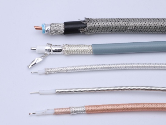
Anatomy of a 90Ω Micro Coaxial Cable
A typical 90Ω micro coaxial cable consists of four main layers:
Center Conductor: Usually silver-plated copper (SPC) or bare copper. A larger diameter lowers resistance but increases capacitance, so a balance is needed for the target impedance.
Dielectric Insulation: This layer defines the single-ended impedance. Materials like foamed PTFE or FEP are common for their low dielectric constant (Dk) and low loss. The dielectric thickness is tightly controlled.
Shielding Layer: Typically a combination of a thin aluminum foil and a tinned copper braid. This dual-layer shield provides >90% coverage for excellent EMI protection and low radiation.
Outer Jacket: A flexible material like PVC or polyurethane that protects the cable from mechanical stress and environmental factors. The choice of jacket affects flexibility, temperature range, and flame retardancy.
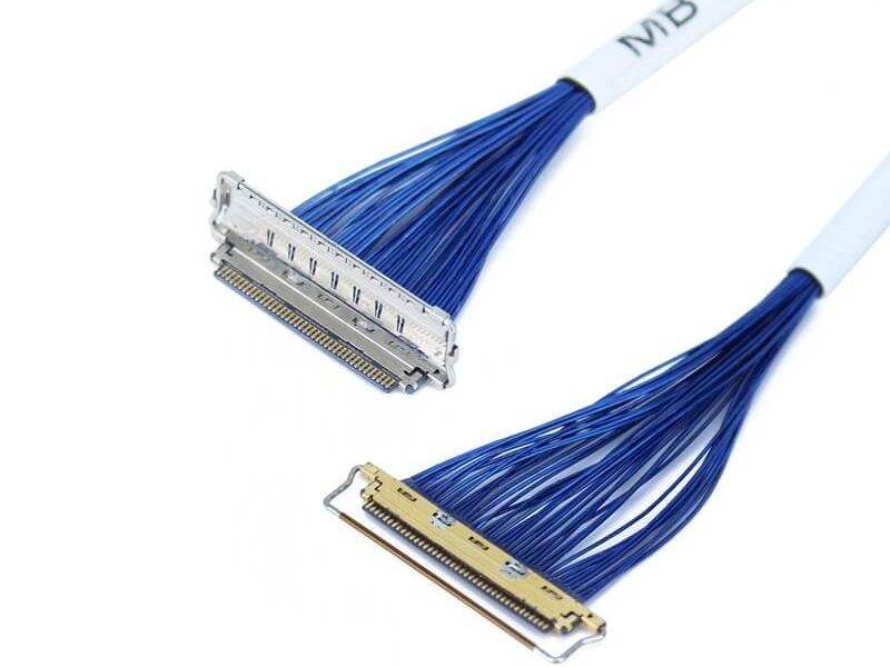
Matching the 90Ω Micro Coax to MIPI Connectors
The performance of the entire MIPI channel is only as good as its weakest link. The transition from PCB trace to connector to cable must be seamless.
Connector Impedance: Choose connectors explicitly specified for 90Ω or 100Ω differential impedance. Popular MIPI micro-coax connectors include I-PEX (e.g., CABLINE® series), Hirose, JAE, and others. Mismatched connectors can cause significant reflections.
Connector Geometry: The pad size, via stub, and routing on the PCB must be designed to match the connector’s impedance profile. Poor matching at the connector interface is a common cause of signal integrity issues.
Cable-to-Connector Termination: The shield must be securely grounded to the connector’s backshell, and the center conductor must be precisely crimped or soldered. Inconsistent termination can create impedance discontinuities and skew between channels.
Channel Length, Loss Budget, and Practical Limits
The maximum reliable length of a 90Ω micro coaxial cable for MIPI depends on several factors:
Data Rate per Lane: Higher speeds (e.g., 4–6 Gbps) have less tolerance for loss.
Number of Lanes: More lanes increase overall channel loss and crosstalk.
Cable Construction: Materials and shielding quality directly impact loss and EMI performance.
General Guidelines:
For 1.5 Gbps D-PHY, a well-designed micro-coax cable can often reach 150 mmwithout significant signal degradation.
For 2.5–4 Gbps, lengths are typically limited to 50–100 mm.
Some specialized systems, like certain embedded vision platforms, use high-quality micro-coax to achieve up to 1 meterfor 4-lane MIPI, but this requires careful design and often involves trade-offs.
Loss Budget Analysis: Engineers should perform a channel loss budget that accounts for the PCB trace, connector, and cable losses. If the loss at the target frequency is too high, options include:
Shortening the cable.
Reducing the data rate or number of lanes.
Using a lower-loss cable construction.
Adding active components like a repeater or retimer.
Micro Coax vs. FPC/Ribbon Cables for MIPI
While FPC/ribbon cables are cheaper and easier to mass-produce, they fall short for high-performance MIPI applications.
Feature
90Ω Micro Coaxial Cable
FPC / Ribbon Cable
Impedance Control
Excellent and consistent due to coaxial structure.
Difficult to control precisely over long lengths and multiple layers.
EMI/Crosstalk
Excellent, with individual shielding for each pair.
Poor, with significant crosstalk between adjacent conductors.
Bandwidth
Supports multi-gigabit per lane speeds reliably.
Performance degrades rapidly at high frequencies.
Flexibility
Good for tight-radius bends in 3D spaces.
Can fatigue or crack if bent repeatedly in tight radii.
Best For
High-resolution cameras, long MIPI runs, noisy environments.
Very short connections on rigid PCBs where cost is critical.
🛠️ Design and Manufacturing Considerations
PCB Layout: Maintain symmetry in differential pairs and minimize stubs. Ensure the impedance of the PCB traces matches the cable and connector (typically 45–50Ω single-ended).
Grounding: Use a solid ground plane near the high-speed signals. Connect the shields of all micro-coax cables to a common ground point on the PCB to avoid ground loops.
Channel-to-Channel Matching: For multi-lane MIPI, ensure the electrical length of each lane is matched to within a few millimeters to prevent skew, which can cause color misalignment or image tearing.
Manufacturing Quality: The quality of the cable assembly process is paramount. Variations in shielding termination, crimping, and soldering can ruin the impedance match. Work with vendors who have proven experience in high-speed MIPI cable assemblies.
Applications of 90Ω Micro Coax in MIPI Systems
Mobile Devices: Smartphones, tablets, and AR/VR headsets use micro-coax to connect high-resolution cameras and displays to application processors in ultra-compact spaces.
Automotive: In-vehicle cameras for ADAS and surround-view systems rely on shielded micro-coax to maintain signal integrity in harsh electrical environments.
Industrial & Embedded Vision: Machine vision cameras and inspection systems use micro-coax to carry MIPI signals between sensors and processing units, often in robotic or moving assemblies.
Edge AI & SBCs: Platforms like the NVIDIA Jetson Orin use micro-coax to connect multiple MIPI cameras, where signal integrity is critical for AI inference.
Key Takeaways for Your MIPI Design
When specifying a 90Ω micro coaxial cablefor your MIPI interface, focus on the entire channel, not just the cable itself. Ensure that the PCB, connectors, terminations, and cable are all designed and specified as a system to meet your performance targets for data rate, length, and EMI.
Mechanical Stress ManagementA. Bending and Shaping GuidelinesSemi-rigid cables are designed for one-time bending. Improper shaping can crack the outer conductor, causing signal leakage or impedance mismatches.
Cable Diameter ...
Confused by technical jargon like “low-loss phase-stable micro-coaxial cable”? You’re not alone. This specialized cable plays a vital role in high-frequency electronics, but its name can be intimidating. Let’...
In the rapidly evolving landscape of microwave systems, the demand for high-performance, reliable signal transmission has never been more critical. From telecommunications and aerospace to medical equipment and industrial testing, micro...
In any setting where cables and wires are present—whether it’s a home, office, industrial facility, or outdoor environment—keeping them organized and securely routed is more than just a matter of tidiness. It’s a critical step in ensuri...
A newly released industry report, compiled by leading market research firm Global Connect Insights, has shed light on the key factors driving competitiveness in the coaxial cable sector. Among the findings, our company’s coaxial cable p...
Underground installation of communication and signal transmission cables is a common practice in many industries, from telecommunications and broadcasting to industrial automation and security systems. However, choosing the right cable ...
Return Loss (RL) is a critical parameter in any RF system, indicating how effectively signal power is transmitted from a source into a load (like an antenna, circuit, or another cable) versus how much is reflected back due to impedance ...
The choice between flexible and semi-rigid micro-coaxial cables hinges on balancing mechanical robustness, electrical performance, and application-specific requirements.
IntroductionMicro-coaxial cables are critical for high-frequen...
nternet Protocol Television (IPTV) has revolutionized how we consume media, delivering live TV, video-on-demand, and interactive content over broadband networks. While fiber-optic and Ethernet cables are often considered the gold standa...
Imagine a cable at the heart of an MRI machine delivering crucial signals, or deep within a satellite enduring the harsh radiation of space. Ordinary cables fail in these extremes. That’s where radiation-resistant miniature coaxial cab...
Coaxial cable assemblies are critical components in telecommunications, aerospace, industrial automation, and consumer electronics, transmitting high-frequency signals with minimal interference. However, corrosion—caused by moisture, ch...
For electricians, network installers, and DIY enthusiasts, locating hidden wires snaking through walls, ceilings, or conduit systems can feel like solving a puzzle without a map. This is precisely where cable toners prove indispensable—...
Micro coaxial cables are widely used in electronics, telecommunications, and high-frequency applications due to their compact size and reliable signal transmission. However, improperly terminating these cables can lead to signal loss, i...
Micro coaxial cable soldering service is a specialized capability that joins ultra‑fine coaxial conductors to connectors or PCB pads with precise impedance control, mechanical reliability, and high‑frequency signal integrity. It is wide...
When selecting micro-coaxial cables for high-temperature applications, understanding the temperature tolerance of PTFE-insulated micro-coaxial cables is critical. Polytetrafluoroethylene (PTFE) is a popular insulation material due...
High-frequency micro coaxial cables are essential for connecting sensitive components in modern electronics like smartphones, radar systems, satellite communications, medical devices, and high-speed digital circuits. One of the most cri...
The Game-Changing Technology
Flexible micro-coaxial cables are revolutionizing electronics by allowing devices to bend and fold without breaking internal connections. These hair-thin cables (often thinner than 0.2mm) maintain strong ...
In the ever-evolving landscape of mobile technology, the development of 6G is on the horizon. With the promise of significantly faster speeds, ultra-low latency, and enhanced connectivity, 6G aims to revolutionize the way we interact wi...
Micro coaxial cables are the unsung heroes of modern military electronics. Packing powerful signal capabilities into an ultra-thin profile, they’re essential for everything from missile guidance systems and radar to ruggedized com...
Coaxial cables are indispensable in telecommunications, broadcasting, and aerospace, where even minor quality flaws can lead to signal loss, system failures, or safety hazards. Hence, strengthening the coaxial cable quality inspection p...
In the realm of microwave radio communication, where signal integrity, compactness, and reliability are paramount, micro-coaxial cables have emerged as a critical component. Microwave radio systems operate at high frequencies ranging fr...
Introduction: The Battlefield Connectivity Imperative
Modern warfare demands unprecedented mobility from soldiers, who routinely carry 15+ kg of electronic gear. Traditional coaxial cables force critical compromises between durabili...
The global shift toward smart infrastructure—encompassing smart grids, intelligent transportation systems, smart buildings, and industrial IoT (IIoT)—has intensified the demand for high-performance connectivity solutions. Among these, m...
In film production, reliable signal transmission is key to capturing high-quality audio and video. Coaxial cables play a vital role here, but choosing the right one and using it properly can be tricky. This guide breaks down everything ...
Neural recording technology has revolutionized our understanding of the brain’s complex functions, enabling breakthroughs in neuroscience research, clinical diagnostics, and neuroprosthetics. At the heart of this technology lies a criti...
Introduction
The rollout of 5G network infrastructure has been a global phenomenon, promising faster data speeds, lower latency, and the ability to connect a vast number of devices simultaneously. As the demand for high – perfo...
The short answer is a resounding yes—coaxial cable assemblies, especially high-performance Micro-Coaxial Cables, are not only compatible with DVR (Digital Video Recorder) systems but also serve as a critical component in ensuring reliab...
In the world of outdoor electrical and communication setups, the significance of a reliable cable cannot be overstated. When it comes to harsh weather conditions, outdoor-rated coaxial cables emerge as the go-to solution for a plethora ...
In the relentless drive for smaller, faster, and more powerful electronics, a silent hero quietly enables success: the micro coaxial cable. These miniature marvels are far more than just tiny wires; they are the critical arteries ...
The rollout of 5G technology is transforming how we connect, promising lightning-fast speeds, near-instantaneous response times (ultra-low latency), and the capacity to link billions of devices. However, harnessing the true power of 5G,...
Introduction to SMA and MCX ConnectorsSMA (SubMiniature version A) and MCX (Micro Coaxial) connectors are widely used in RF and high-frequency applications, including telecommunications, aerospace, and IoT devices. These connectors ensu...
Introduction
Micro-coaxial cables have become the backbone of modern high-frequency signal transmission, from medical devices to 5G networks. Since 2000, shielding techniques have undergone revolutionary changes to meet escalating de...
In the rapidly evolving landscape of high‑frequency signal transmission, the micro coaxial cable has emerged as a critical component for industries that demand precision, reliability, and miniaturization. From the depths of aerospace sy...
In response to the increasingly diverse and specialized needs of various industries for coaxial cables, our factory is proud to officially launch a comprehensive coaxial cable customization service. This service aims to provide tailored...
IntroductionThe rapid evolution of augmented reality (AR) and virtual reality (VR) headsets is pushing hardware components to their limits. One critical yet often overlooked element is the micro-coaxial cable, a tiny but vital part res...
Introduction
Imagine your internet cutting out during an important video call, or a medical robot failing mid-surgery due to undetected cable damage. Micro-coaxial cables (micro-coax) – the hair-thin wires powering everything from 5G...
For those in the market for coaxial cables, the warranty period is undoubtedly a crucial factor. It serves as a direct guarantee for your post-purchase rights and interests, providing a safety net when unexpected issues arise with the p...
In high-speed, high-density electronic devices, the quality of interconnection often determines the final performance. Micro coaxial cable bulk supplyis no longer just a commodity; it is a critical factor for ensuring stable signal tran...
In the ever – evolving field of coaxial cable manufacturing, the adoption of new materials has become a key driver of progress. Our company is proud to be at the forefront of this innovation by integrating a cutting – edge n...
In the high-stakes world of medical technology, signal integrity, durability, and electromagnetic interference (EMI) resistance are non-negotiable. Coaxial cables, with their unique design and shielding capabilities, have emerged as a c...
In LVDS (Low Voltage Differential Signaling) display systems, Micro-coaxial Cable (also referred to as Micro Coax Cable) stands out as an optimal solution for high-resolution, high-reliability signal transmission. Designed to meet the str.
Meta Description: Discover premium RF micro coaxial cables engineered for high-frequency signal transmission in compact devices. Explore specs, applications, and benefits for telecom, medical, and aerospace industries.
.
Contact Us Micro Coaxial Cable factory-(FRS).
Feel free to reach out to us for any inquiries or orders