Micro coaxial cables are the unsung heroes of modern electronics, silently transmitting critical signals in everything from medical devices and drones to high-speed data links and miniature cameras. But with so many variations available, selecting the right one can feel overwhelming. Choose poorly, and you risk signal loss, interference, or even device failure. This guide cuts through the complexity, giving you the practical knowledge to confidently select the perfect micro coax cable for your specific needs.
Why Getting the Right Micro Coax Matters
Micro coaxial cables (often called “micro coax”) are miniature versions of traditional coaxial cables. They consist of:
- Center Conductor: Carries the signal.
- Dielectric Insulation: Surrounds the conductor, maintaining spacing and electrical properties.
- Outer Shield (Braided and/or Foil): Blocks electromagnetic interference (EMI) and acts as the signal return path.
- Outer Jacket: Protects the internal components from physical damage and environmental factors.
Choosing incorrectly can lead to:
- Degraded Signal Quality: Blurry video, slow data, unreliable control signals.
- EMI/RFI Interference: Noise disrupting your signal from other devices or the environment.
- Mechanical Failure: Cables breaking due to repeated bending or harsh conditions.
- Costly Rework: Having to replace cables after integration is time-consuming and expensive.
Key Factors to Consider When Choosing Micro Coax:
- Frequency & Bandwidth Requirements:
- This is CRITICAL. What is the highest frequency signal the cable needs to carry? (e.g., 1 GHz for HD-SDI video, 6 GHz for USB 3.2, 10+ GHz for radar or high-speed data links).
- Higher frequencies = Higher signal loss (attenuation). Cables are rated for maximum usable frequency. Always choose a cable rated higher than your maximum signal frequency. Check the cable’s datasheet for its attenuation (dB loss per meter/100ft) at your target frequency – lower dB loss is better.
- Impedance Matching:
- Most Common: 50 Ohm (standard for RF, wireless, test equipment, many digital systems) and 75 Ohm (standard for video like SDI, CCTV, broadcast).
- Why it Matters: Mismatched impedance between your cable, source device, and load device causes signal reflections. These reflections distort the signal, leading to errors and reduced performance. Ensure your cable’s impedance matches the impedance of the connectors and the circuits it connects to.
- Signal Loss (Attenuation):
- As mentioned, signal strength decreases over cable length and with increasing frequency.
- Key Influencers: Cable diameter (thinner cables generally have higher loss), dielectric material quality, conductor material (solid vs. stranded copper).
- Action: Calculate the total loss expected for your cable length at your operating frequency (using datasheet values). Ensure the received signal strength at the end is sufficient for your receiver’s sensitivity. For long runs or high frequencies, thicker cables or lower-loss dielectrics (like PTFE) are essential, even if bulkier.
- Shielding Effectiveness:
- How well does the cable protect the inner signal from external interference (EMI/RFI) and prevent the signal from radiating out and interfering with other devices?
- Common Types: Braid only (good flexibility, moderate shielding), Foil only (excellent high-frequency shielding, less flexible), Foil + Braid (best overall shielding, common in demanding applications).
- Choose Based On Environment: High-noise environments (industrial machinery, motors, wireless transmitters) demand foil+braid. Less noisy environments might suffice with braid-only.
- Flexibility & Bend Radius:
- Static vs. Dynamic: Will the cable be fixed in place, or will it be constantly flexing/bending (e.g., inside a robot arm, on a moving camera gimbal)?
- Dynamic Applications: Require highly flexible cables specifically designed for repeated bending. Look for stranded center conductors, specialized flexible dielectrics, and often a higher strand-count braid. Critical: Know the cable’s minimum bend radius (the tightest curve it can handle without damage) and ensure your application respects it. Exceeding this damages the cable internally.
- Environmental Conditions:
- Temperature Range: Will the cable experience extreme heat (near engines, industrial processes) or cold (outdoor equipment)? Ensure the jacket and dielectric materials are rated for your operating temperature range.
- Chemicals/Oils: Exposure to solvents, fuels, or lubricants? Choose cables with chemical-resistant jackets (e.g., specific PVC blends, Polyurethane, Teflon).
- Abrasion: Will it rub against surfaces? Abrasion-resistant jackets are key.
- Moisture/Water: Outdoor or damp environments? Look for moisture-resistant or waterproof jackets and potentially flooded-core designs.
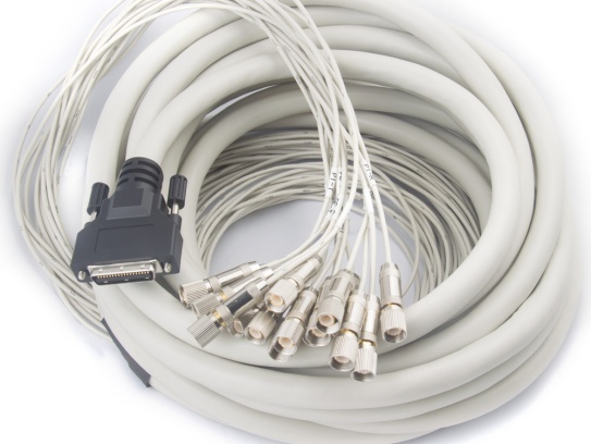
- Connectors:
- Match Exactly: The cable must terminate in connectors compatible with your devices (e.g., MMCX, MCX, SMP, SMA, Hirose U.FL, IPEX). Mismatched connectors won’t fit or work.
- Termination Quality: Poorly crimped or soldered connectors are a major failure point, especially on tiny micro coax. Ensure high-quality termination, often best done by specialists or using pre-terminated assemblies.
- Cable Diameter & Weight:
- Space is often extremely limited in micro-coax applications (drones, wearables, endoscopes). Measure your available space carefully.
- Thinner cables are lighter and fit tighter spaces but usually have higher signal loss and less shielding. Find the best compromise for your size/weight budget and performance needs.
Application-Specific Tips:
- HD/UHD Video (SDI): Prioritize 75 Ohm impedance, low attenuation at high frequencies (3G/6G/12G-SDI), excellent shielding (foil+braid), and appropriate flexibility. RG179 is common for shorter runs.
- High-Speed Digital Data (USB 3.x, PCIe, Ethernet): Requires precise impedance control (often 90 Ohm differential pairs within the cable), very low loss at multi-GHz frequencies, and excellent shielding. Look for cables specifically rated for the standard (e.g., “USB 3.2 Gen 2”).
- RF/Wireless (Antennas, GPS, Cellular): 50 Ohm impedance is standard. Critical low loss at the operating frequency (e.g., 1.5 GHz for GPS, 2.4/5 GHz for WiFi/BT, higher for 5G). Shielding is paramount.
- Medical Devices: Often requires biocompatible jackets, high flexibility, small diameter, and reliability. May need specific sterilization compatibility (e.g., autoclave, EtO, gamma).
- Robotics/Drones: Demands high flexibility and a tight bend radius for dynamic movement, plus durability against abrasion and potentially vibration. Lightweight is often crucial for drones.
- Industrial Sensors/Controls: Needs robust shielding against heavy EMI, chemical/oil resistance, and wide temperature tolerance.
The Golden Rule: Consult the Datasheet & Test!
- Never Guess: Always obtain and carefully review the manufacturer’s datasheet for the specific cable series you are considering. It contains the critical specs: impedance, attenuation curves, frequency rating, shielding type, bend radius, temperature range, jacket material, dimensions, etc.
- Order Samples: Whenever possible, order cable samples and test them in your actual application or a representative mock-up. Check signal integrity (oscilloscope, network analyzer), measure loss, and test mechanical durability (flexing, bending). This is the best way to avoid costly surprises later.
Avoiding Common Pitfalls:
- Prioritizing Price Over Performance: Cheap, generic cables often have inconsistent impedance, poor shielding, and high loss. This leads to unreliable performance. Invest in quality from reputable suppliers.
- Ignoring Bend Radius: Forcing a cable into a tighter bend than specified causes immediate or gradual internal damage, increasing loss and causing failure.
- Impedance Mismatch: Using a 50-ohm cable in a 75-ohm system (or vice-versa) guarantees signal reflections and degraded performance.
- Underestimating Loss: Not calculating attenuation for your specific length and frequency can leave you with a signal too weak to be usable at the receiver.
- Neglecting the Environment: A cable perfect for a lab bench might melt near a motor or crack in freezing temperatures.