
Micro Coaxial Cable factory-(FRS)
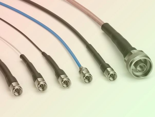
Micro-coaxial connectors are essential for high-frequency signals in devices like smartphones, WiFi routers, and medical equipment. A single faulty solder joint can cause frustrating signal loss, data drops, or device failure. Don’t let tiny defects ruin your project! Learn to identify and fix these common micro-coaxial soldering issues like a pro.
Appearance: Dull, grainy, or lumpy surface instead of smooth and shiny.
Causes: Wrong soldering iron temperature, dirty tip, insufficient heat time, or moving parts before solidification.
Result: Cracked connection causing intermittent signals or complete failure.
Fix:
Prevention: Preheat your iron fully, keep the tip tinned, and hold components steady until cool.
Appearance: Accidental solder blobs connecting adjacent connector pins or shields.
Causes: Too much solder, shaky hands, or poor alignment.
Result: Short circuits preventing proper signal transmission – often visible as zero signal output.
Fix:
Prevention: Apply solder sparingly and use high-quality flux to control flow. Use magnifying glasses or microscope.
Appearance: Thin, concave, or incomplete coverage on pads/pins.
Causes: Too little solder applied, poor flux activity, or wrong thermal profile.
Result: Crack-prone joints with weak electrical connections leading to dropouts.
Fix:
Prevention: Ensure surfaces are clean pre-soldering. Use no-clean flux to improve wetting.
Appearance: Copper pad or trace peeling off the PCB surface.
Causes: Excessive heat, prolonged iron contact, or physical stress during assembly.
Result: Permanent circuit damage – no physical/electrical connection possible.
Fix:
Prevention: Use temperature-controlled irons, avoid holding heat >3-5 seconds, and handle connectors gently.
Appearance: Melted plastic housing, deformed center pins.
Causes: Excessive soldering temperature or time.
Result: Ruined connector requiring complete replacement.
Fix: Replace the connector entirely – but be extremely cautious not to overheat again!
Prevention: Keep iron tip temperature ≤350°C. Use thermal clips (“alligator clips”) on connector pins to sink heat away from the plastic.
Pro Tip: Always follow manufacturer thermal specs. Some micro-coax connectors specify max soldering durations!
Mastering micro-coaxial soldering takes practice, but spotting these defects early prevents catastrophic failures. Keep your joints clean, hot (but not too hot!), and solid. Invest in a good temperature-controlled soldering station and flux pen – your router, drone, or IoT device will thank you.
Found a stubborn problem? Share in the comments! For advanced connectors (IPEX/U.FL), see our full guide on strain-relief techniques.
Our factory offers high-quality products at competitive prices
H1: Precision Instrument Micro-Coax – Engineered for Critical Signal Integrity Meta Description: Discover Precision Instrument Micro-Coax: Miniature coaxial cable solution optimized for high-frequency signal transmissio.
OverviewMicro-Coax for HD Video is a cutting-edge coaxial cable engineered to deliver uncompromised high-definition video quality across professional and industrial applications. Designed for reliability, precision, and versatility,.
Feel free to reach out to us for any inquiries or orders