
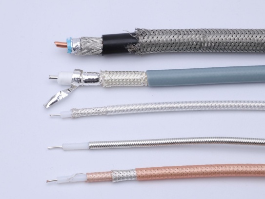
Micro Coaxial Cable factory-(FRS)
In the realm of electronic engineering, impedance matching in transmission lines stands as a vital concept that underpins the efficient operation of countless systems. Simply put, it is a state where the load impedance matches the characteristic impedance of the transmission line, facilitating the maximum transfer of power.
Impedance matching is of paramount importance in transmission lines. When impedance is not matched, reflection occurs. This reflection leads to a series of adverse effects. Signal attenuation is a common consequence, where the strength of the signal diminishes as it travels along the line. Signal distortion is another issue, causing the signal to lose its original shape and integrity, which can result in errors in data transmission or misinterpretation of the signal by receiving devices. In severe cases, the reflected energy can even damage sensitive components of the system, such as transmitters or receivers.
For example, in high-frequency communication systems, even a small mismatch can lead to significant signal loss, reducing the range and reliability of the communication. In power transmission, impedance mismatch can cause inefficient power transfer, wasting energy and increasing costs.
To understand the principle of impedance matching, we need to delve into some basic circuit theory concepts. Transmission lines can be analyzed using transmission line equations, which describe the behavior of voltage and current along the line. The characteristic impedance (Z₀) of a transmission line is a key parameter that depends on the physical properties of the line, such as its inductance, capacitance, and resistance per unit length.
The reflection coefficient (Γ) is a measure of the amount of signal reflected at a junction between a transmission line and a load. It is calculated as (Z_L – Z₀) / (Z_L + Z₀), where Z_L is the load impedance. When Z_L equals Z₀, the reflection coefficient is zero, indicating no reflection, and this is the state of perfect impedance matching. In this state, all the incident power is transferred to the load, maximizing power transfer efficiency.
There are several methods to achieve impedance matching in transmission lines, each with its own working principles, applicable scenarios, and pros and cons.
Impedance transformers are devices designed to convert one impedance value to another. They work based on the principle of electromagnetic induction. A common type is the transformer with a turns ratio, where the ratio of the primary to secondary turns determines the impedance transformation ratio. For example, if the turns ratio is N₁:N₂, the impedance ratio is (N₁/N₂)².
Impedance transformers are suitable for applications where a fixed impedance transformation is required, such as in power supplies and audio systems. Their advantages include high efficiency at the designed frequency and good isolation between the input and output. However, they have a limited frequency range and may be bulky at lower frequencies.
Stub matching involves adding a short-circuited or open-circuited section of transmission line (a stub) to the main transmission line at a specific point. The length and position of the stub are chosen to cancel out the reactive component of the load impedance, resulting in a matched condition.
This method is widely used in high-frequency applications, such as microwave systems. It is relatively simple and cost-effective to implement. However, it is frequency-sensitive, meaning it works well only at a specific frequency or a narrow frequency band. Adjusting the stub length and position can be tricky, especially in complex systems.
Impedance matching finds extensive applications in various fields. In 射频通信 (RF communication), it ensures that the signal from the transmitter is efficiently transferred to the antenna, maximizing the radiation of the signal. Without proper matching, a significant portion of the signal would be reflected back, reducing the transmission range and quality.
In radar systems, impedance matching is crucial for the accurate detection and ranging of targets. The radar transmitter needs to deliver maximum power to the antenna, and the received signal from the antenna must be efficiently transferred to the receiver for processing. Impedance mismatch can lead to reduced sensitivity and inaccurate measurements.
In audio systems, impedance matching between amplifiers and speakers ensures that the amplifier can deliver maximum power to the speakers, resulting in high-quality sound reproduction. A mismatch can cause distortion and reduce the efficiency of the system.
In conclusion, understanding impedance matching in transmission lines is essential for anyone working in electronic engineering and related fields. By ensuring proper impedance matching, we can maximize power transfer, minimize signal loss and distortion, and ensure the reliable operation of electronic systems.
Our factory offers high-quality products at competitive prices
Meta Description: Discover premium RF micro coaxial cables engineered for high-frequency signal transmission in compact devices. Explore specs, applications, and benefits for telecom, medical, and aerospace industries. .

IntroductionThe High-Temperature Resistant Micro-Coaxial Cable is a cutting-edge connectivity solution engineered to deliver exceptional performance in extreme thermal environments. Combining precision engineering with advanced mate.
Feel free to reach out to us for any inquiries or orders