Micro Coaxial Cable factory-(FRS)

What Is Low Loss Micro Coaxial Cable for VR Headset and Why It Matters - Micro Coaxial Cable factory-(FRS)

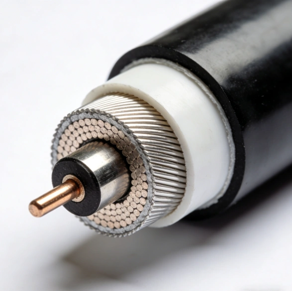
Micro Coaxial Cable-Micro Coaxial Cable factory-(FRS)-FRS


INFO

Why VR headsets need low loss micro coaxial cable

High‑resolution, high‑frame‑rate VR depends on moving massive amounts of image data across very short, highly constrained interconnects inside the headset. Traditional FPC/FFC or round wires often can’t maintain stable impedance and shielding when bent repeatedly in tight spaces, leading to reflections, crosstalk, and EMI susceptibility. Low loss micro coaxial cable—with its controlled characteristic impedance, excellent shielding, and small diameter—keeps insertion loss and return loss low while allowing dense, flexible routing. Typical micro‑coax outer diameters range from about 0.22–1.16 mm, with common AWG sizes from 30–46for the center conductor, making them ideal for the hinge and goggle‑to‑display paths in VR headsets where space and signal integrity are both critical

What makes a micro coaxial cable “low loss”

“Low loss” in this context means minimizing signal degradation across the required bandwidth and length. Key contributors include:

  • Characteristic impedance consistency: Stable, uniform impedance along the length reduces reflections and return loss. Micro‑coax structures inherently support this better than flat flex in high‑speed links.
  • Conductor and dielectric selection: Larger effective conductor cross‑section (for a given impedance) and low‑loss dielectrics reduce resistive and dielectric losses.
  • Shielding effectiveness: A robust outer conductor (braid/foil or seamless tube) suppresses EMI and crosstalk, preserving image quality.
  • Bend radius and flex life: Even when bent, the electrical performance remains predictable; this is essential for headband hinges and repeated donning/removal.These traits are why micro‑coax is favored over FPC/FCC in high‑speed, high‑density interconnects, particularly when the signal path includes dynamic flexing2.

Bandwidth and data rate reality for VR

Display interfaces in VR are trending toward multi‑gigabit, multi‑lane links. For example, driving 4K@60Hzcan require on the order of ~12 Gbps, while 8K@60Hzcan exceed ~48 Gbpsdepending on chroma sampling and compression. Practical micro‑coax solutions for internal VR links are commonly designed with bandwidths in the 6–12+ GHzrange to support these data rates over the very short runs inside the headset. Maintaining low loss over these frequencies ensures stable images with minimal jitter, sparkles, or color banding

Connector and routing considerations inside the headset

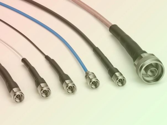
The industry standard for many VR headset interconnects pairs micro‑coax with miniature, high‑density board‑to‑board connectors. Examples include the I‑PEX CABLINE‑VSfamily (e.g., 0.5 mm pitch, available in 30‑pinconfigurations) and the I‑PEX 20497‑026T‑30(also 0.3 mm pitch, multiple pin counts). These connectors are designed for high‑speed, low‑profile routing and are widely used where space is at a premium. Typical micro‑coax used with such connectors spans AWG #44–#38, enabling tight bends and dense harnessing while preserving signal integrity. When combined with proper strain relief and fixed routing points, these assemblies deliver the mechanical and electrical stability VR headsets demand

Design checklist for low loss micro coaxial in VR headsets

  • Impedance control and TDR verification: Target a single, uniform impedance (commonly 50 Ωfor many high‑speed links) and verify with TDR across the entire length and all channels.
  • Frequency margin: Size the cable and shielding for at least the required Nyquist frequency with margin for manufacturing variation and assembly tolerances.
  • Shielding and EMI: Use dual‑shield (foil + braid) or high‑coverage braid to suppress near‑end and far‑end crosstalk in densely packed harnesses.
  • Bend radius and flex life: Respect the manufacturer’s minimum bend radius; add “service loops” and strain relief to prevent migration of the neutral axis during flex.
  • Length budgeting: Keep high‑speed micro‑coax runs as short as possible; model insertion loss and eye‑diagram margins early to avoid late‑stage surprises.
  • Connector and crimp/weld quality: Use the specified crimp/weld geometry and controlled process; verify contact resistance and continuity across all lines.
  • Mechanical protection: Route away from sharp edges and moving parts; consider anti‑fray sleeves or localized stiffeners at stress points.
  • Signal‑to‑noise and microphonics: Where cables are near moving assemblies, consider materials and construction that reduce microphonic noise and triboelectric effects.These practices, when applied during layout and prototyping, significantly reduce the risk of EMI, skew, and insertion‑loss‑driven artifacts in the rendered image26.

When low loss micro coax is the right choice—and when it isn’t

Use low loss micro coax when you need multi‑gigabit, impedance‑controlled, shielded links in a small, dynamic space—exactly the case for VR headset display and camera interconnects. It outperforms FPC/FCC in high‑speed, high‑density, and high‑flex scenarios. However, if the application is cost‑driven with modest bandwidth needs and minimal flex, simpler flat flex or twisted‑pair solutions may suffice. For very high‑frequency, fixed installations (e.g., certain RF paths), semi‑rigid coax with seamless outer conductors can offer even lower loss and superior shielding, albeit with less mechanical flexibility

Engineering insights you can act on

  • Trade diameter for loss and flexibility: Thinner micro‑coax reduces bulk but raises loss per unit length; model the loss budget early to choose the right AWG and dielectric.
  • Mind the shield: Higher braid coverage and proper shield termination at both ends are essential for EMI control and consistent return loss.
  • Simulate before you build: Use vendor‑supplied S‑parameter models (or build test coupons) to evaluate insertion loss, return loss, and crosstalk across your exact length and bend geometry.
  • Assembly discipline matters: Consistent strip length, precise shield termination, and controlled solder/weld profiles prevent parametric drift and intermittent failures.
  • Plan for serviceability: Include test pads or loopbacks in the harness to enable in‑line validation and reduce rework when debugging display or camera channels.

By understanding what “low loss” means in the context of micro coax—and how it directly impacts image quality, EMI, and mechanical reliability—you can make informed trade‑offs between size, bandwidth, and cost. In VR headsets, where every millimeter and every gigahertz counts, low loss micro coaxial cable isn’t just a component choice; it’s a foundational enabler of immersive, artifact‑free visuals.

low loss micro coaxial cable

FAQ

NEWS

More Products

Our factory offers high-quality products at competitive prices

High-Temperature Resistant Micro-Coaxial Cable

High-Temperature Resistant Micro-Coaxial Cable

IntroductionThe ​High-Temperature Resistant Micro-Coaxial Cable is a cutting-edge connectivity solution engineered to deliver exceptional performance in extreme thermal environments. Combining precision engineering with advanced mate.

Precision Instrument Micro-Coax

Precision Instrument Micro-Coax

H1: Precision Instrument Micro-Coax – Engineered for Critical Signal Integrity Meta Description: Discover Precision Instrument Micro-Coax: Miniature coaxial cable solution optimized for high-frequency signal transmissio.

Contact Us Micro Coaxial Cable factory-(FRS).


Feel free to reach out to us for any inquiries or orders

Call Us

Have a question? Give us a call!

+861881875005

Email Us

Send us an email and we'll get back to you soon.

sales@custom-cable-assemblies.com
       
Home Products Contact