Micro Coaxial Cable factory-(FRS)

What is a micro coaxial cable with I-PEX 20373 connector and how does it work - Micro Coaxial Cable factory-(FRS)

Micro Coaxial Cable-Micro Coaxial Cable factory-(FRS)-FRS


INFO

Overview and definition

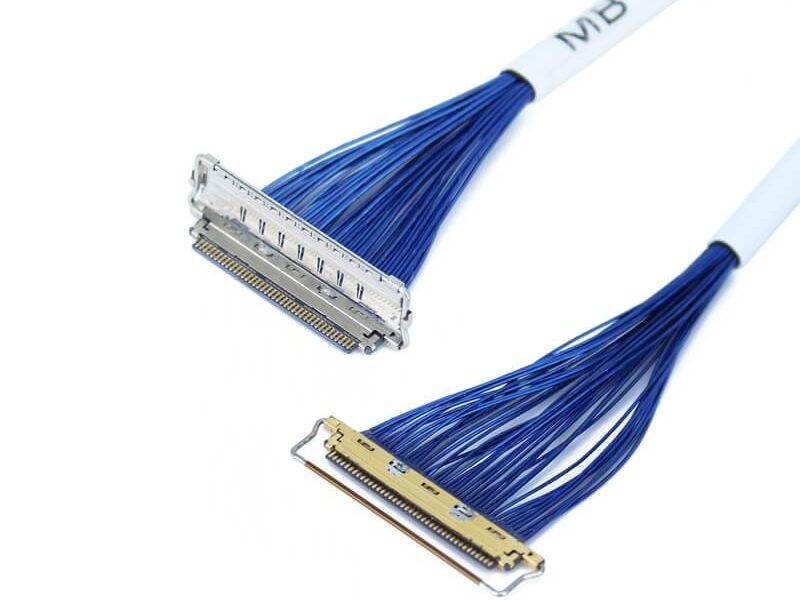
A micro coaxial cable with an I-PEX 20373 connector is a miniaturized, shielded interconnect built to carry high‑speed differential or single‑ended signals between tightly spaced PCBs or modules. The I‑PEX 20373 belongs to the CABLINE‑SSfamily and uses a 0.4 mmfine pitch with a vertical mating orientation. Typical configurations include 10–50 pins, with a mated height around 1.65–1.85 mm, and it is widely used for display and cameralinks in notebooks, tablets, medical devices, and flat‑panel displays. The connector’s compact form factor and robust construction make it suitable for high‑density, high‑bandwidth internal connections where space and signal integrity are critical.

How it works

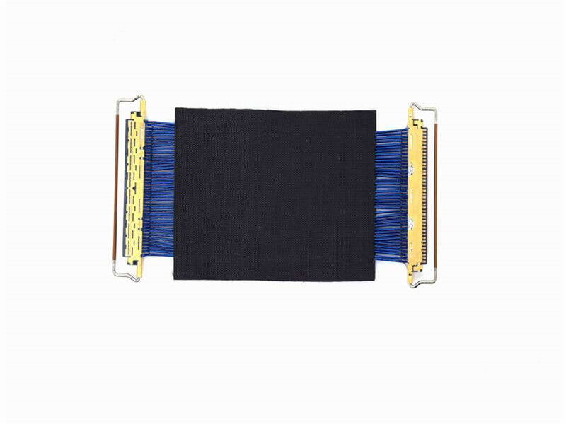
At the heart of the assembly is the coaxial structure: a central conductor is surrounded by a dielectric, an outer conductor (shield), and an outer jacket. In the I‑PEX 20373, each signal contact is effectively a tiny coax, and the connector maintains this controlled impedance across all pins. The outer shieldis terminated to the connector housing, which must be well‑grounded to the PCB to preserve shielding effectiveness and reduce EMI. When mated, the receptacle and plug contacts align precisely, and the connector’s mechanical features—such as the W‑Point dual‑contactarrangement—help ensure low contact resistance and stable retention under vibration and repeated mating cycles. This architecture allows the cable to carry high‑speed signals with minimal crosstalk and insertion loss while withstanding the tight routing and dynamic motion often found in hinge or sliding mechanisms.

Key specifications and variants

ParameterTypical value or rangeNotes
Series and familyI‑PEX 20373 (CABLINE‑SS)High‑density micro‑coax
Pitch0.4 mmFine‑pitch, vertical mating
Pin count10, 14, 20, 30, 32, 35, 40, 50Common options
Mated height1.65 mm (nominal) / 1.85 mm (max)Vertical clearance
OrientationVertical (plug‑in)Suitable for board‑to‑wire/board
Applicable wireAWG #38–#46Depends on cable/impedance plan
Current capabilitySupports larger current (e.g., AWG #34option)Check current derating with length
Matching receptacle20374‑RxxE‑31Example: 20374‑R14E‑31 mates with 20373‑R14T‑06
Typical useDisplay/ camerainterconnectsNotebooks, tablets, medical displays

These parameters reflect common, production‑ready options for the 20373 family and are useful when defining BOMs and stack‑ups.

Signal integrity and design considerations

  • •Impedance control and materials: Maintain consistent controlled impedanceacross all conductors. Use high‑purity copper or copper‑alloy conductors and low‑loss dielectrics (e.g., PTFE/PE) to reduce attenuation. The choice of AWG #38–#46allows balancing flexibility, loss, and current needs.
  • •Shielding effectiveness: Multi‑layer shields (braid + foil) and a continuous ground path through the connector housing minimize EMI and maintain signal clarity, especially for dense, high‑speed links.
  • •Mechanical routing: Maintain uniform bend radii and avoid tight 90° folds. In hinge or rotating designs, ensure strain relief at both the connector and the PCB transition to prevent shield discontinuities and contact wear.
  • •Grounding and return paths: Provide low‑inductance ground vias adjacent to pads, and connect the connector shell to the chassis/reference ground plane to control common‑mode noise.
  • •Length planning: Longer lengths increase insertion loss and skew; keep differential pairs matched in length and route them together to control differential‑to‑common mode conversion.These practices help the micro coax + I‑PEX 20373 deliver stable performance across temperature, vibration, and flexing conditions.

Common applications and mating ecosystem

  • •Applications: The 20373 is prevalent in notebook and tablet displays, medical displays, professional/security cameras, and other devices that require high‑density, high‑bandwidth interconnects in confined spaces. Its vertical mating and narrow profile suit board‑to‑wireand board‑to‑boardrouting through tight clearances.
  • •Mating parts: Typical receptacles include the 20374‑RxxE‑31series (e.g., 20374‑R14E‑31for the 14‑pinvariant). Always match the exact part number for mechanical, electrical, and height compatibility.
  • •Industry context: Within the broader family of I‑PEX micro‑coax solutions, other series (e.g., MHF I) address even higher frequencies (to about 9 GHz) and different mated heights (to about 2.5 mm). While 20373 targets display/camera links, understanding these alternatives helps when system bandwidth or Z‑height budgets differ.These application notes and part cross‑references are drawn from current production listings and family overviews.

Selection checklist and best practices

  • •Pin count and assignment: Start with the exact pin countand signal map; verify differential pairs, grounds, and any sideband/control lines.
  • •Mechanical envelope: Confirm the 0.4 mmpitch and ~1.65–1.85 mmmated height fit within your stack‑up and hinge clearance.
  • •Cable and AWG: Choose AWG #38–#46based on required loss budget, flexibility, and current. For higher current branches, consider larger‑gauge options where feasible.
  • •Shielding and EMI: If the environment is noisy, prefer higher shield coverage and continuous ground connections; consider 360° shield options if offered in related series.
  • •Mating and durability: Pair the 20373 plug with the correct 20374receptacle. Validate mating/unmating cycles, retention force, and any locking features in your mechanical design.
  • •Assembly and test: Use controlled‑impedance tooling and processes for both cable preparation and connector termination. Perform TDR/S‑parameter characterization and system‑level EMI/EMC validation.Following this checklist reduces integration risk and ensures the micro coax + I‑PEX 20373 meets both electrical and mechanical targets.

FAQ

NEWS

More Products

Our factory offers high-quality products at competitive prices

Industrial Micro-Coaxial Wiring

Industrial Micro-Coaxial Wiring

Meta Description: Discover the advanced features and benefits of Industrial Micro-Coaxial Wiring—engineered for precision, durability, and high-speed signal transmission in industrial environments. ​What is Industrial Micro-Co.

LVDS Micro Coaxial Cable

LVDS Micro Coaxial Cable

In LVDS (Low Voltage Differential Signaling) display systems, Micro-coaxial Cable (also referred to as Micro Coax Cable) stands out as an optimal solution for high-resolution, high-reliability signal transmission. Designed to meet the str.

Contact Us Micro Coaxial Cable factory-(FRS).


Feel free to reach out to us for any inquiries or orders

Call Us

Have a question? Give us a call!

+861881875005

Email Us

Send us an email and we'll get back to you soon.

sales@custom-cable-assemblies.com
       
Home Products Contact