Micro Coaxial Cable factory-(FRS)

What is a micro coaxial cable and how does it differ from FPC cable in high-speed signal applications - Micro Coaxial Cable factory-(FRS)

Micro Coaxial Cable-Micro Coaxial Cable factory-(FRS)-FRS


INFO

Micro coaxial cable is a miniaturized coaxial interconnect built to carry high‑speed, high‑frequency signals in extremely confined spaces. Each conductor is surrounded by a precise dielectric and a continuous outer shield, enabling tight impedance control and excellent electromagnetic shielding in a tiny form factor. Typical micro‑coax assemblies have an outer diameter of about 0.22–1.16 mm, with center conductors ranging from AWG 30–46(about 0.30 mmdown to 0.048 mm), and are widely used where size, signal integrity, and EMI control are critical, such as in mobile devices, medical imaging, and high‑speed test equipment. In many high‑speed links, each differential pair or signal lane is implemented as an individual micro‑coax to preserve isolation and impedance. This contrasts with FPC/FFC, which routes multiple conductors side‑by‑side with a common laminate dielectric and a single overall shield, making them more economical for lower‑speed or less noise‑sensitive paths

How micro coax and FPC differ in high‑speed signal applications

AspectMicro coaxial cableFPC/FFC
Shielding and crosstalkEach signal has its own shield, suppressing intra‑ and inter‑pair coupling; excellent EMI controlShared laminate and ground; more vulnerable to crosstalk and external EMI
Impedance controlGeometry tightly controlled for stable single‑ended or differential impedance (e.g., 50 Ω or 100 Ω differential)Impedance depends on overall stackup and trace geometry; harder to control precisely at multi‑gigabit speeds
Insertion loss and bandwidthLow loss with stable dielectric; practical links can reach multiple Gbps per lane and beyondHigher loss at high frequency due to dielectric and line‑to‑line coupling; bandwidth limited by length and stackup
Mechanical behaviorVery small bend radius and good fatigue life; stable when flexedFlexible but more prone to impedance shift and wear when repeatedly flexed; less predictable at high speed
EMI/EMCSuperior shielding continuity; easier to pass radiated emissions limitsRequires careful stackup, guard traces, and overall shielding; more iterations in EMC
Typical useMIPI CSI‑2, LVDS, high‑speed camera/display links, RF modules, test fixturesLow‑speed jumpers, non‑critical interconnects, cost‑sensitive assemblies

These differences become decisive as data rates climb into the multi‑gigabit regime. For example, camera/display and embedded vision systems increasingly adopt micro‑coax to maintain eye‑opening and reduce EMI in compact, high‑density designs

When to choose micro coax and when FPC makes sense

  • •Choose micro coax when you need:
    • •Multi‑gigabit per‑lane performance with low jitter and low loss over practical cable lengths.
    • •Maximum EMI control and minimal crosstalk in dense, noisy environments.
    • •Reliable performance through small bend radii or dynamic flexing (e.g., hinges, gimbals).
    • •Precise, repeatable impedance in each differential pair or single‑ended high‑speed lane.
    • •Examples: MIPI CSI‑2/SLVS‑EC camera modules, eDP/DisplayPort links in thin devices, high‑speed test fixtures, and medical/industrial imaging678.
  • •Choose FPC/FFC when you need:
    • •Cost‑effective, ultra‑thin jumpers for low‑speed or medium‑speed signals.
    • •Simple, flat routing with large pin counts in static applications.
    • •Short interconnects where EMI is manageable and assembly simplicity is a priority12.

Designing with micro coax for high‑speed success

  • •Match the electrical interface: many image/data links are 50 Ω single‑endedor 100 Ω differential; keep the cable and connector impedances aligned and control return paths. Use the connector’s reference plane and keep the shield continuous to the chassis/ground.
  • •Control length and loss: insertion loss rises with frequency and length. Use the lowest‑loss dielectric you can (e.g., low‑loss PTFE/FEP), minimize unnecessary length, and avoid unnecessary vias or transitions that add discontinuity.
  • •Manage the mechanical path: respect the manufacturer’s minimum bend radius and strain relief guidelines. Use support combs/clips near connectors to reduce fatigue on the micro‑coax solder joints.
  • •Prioritize EMI/EMC: choose high‑coverage shields (braid + foil), ensure 360° shield continuity at the connector, and ground the shield at both ends without creating ground loops. Route away from switching power and clock sources.
  • •Verify with data, not just specs: request S‑parameters (S11/S21), TDR impedance profiles, and eye diagrams from your supplier; correlate them with your channel budget. For MIPI/SLVS‑EC, simulate the complete channel (sensor/FPGA/SerDes, connectors, and cable) to confirm margin678.

Connector and ecosystem choices

  • •Use micro‑coax connectors designed for high‑speed, such as I‑PEX CABLINE, HRS, JAE, and KELfamilies. These offer fine pitches (e.g., 0.4 mm, 0.3 mm), low‑profile options, and some with full 360° shielding (e.g., I‑PEX ZenShield). Match the connector’s impedance, mating height, and pinout to your PCB and cable to avoid surprises.
  • •Plan for manufacturability: micro‑coax terminations require precise center‑conductor positioning and consistent shield grounding. Ask for process capability data (e.g., placement/termination repeatability) and, if possible, sample destructive and non‑destructive analyses (cross‑sections, pull tests) to qualify the build3818.

Real‑world examples and achievable performance

  • •Embedded vision: MIPI CSI‑2 camera modules with micro‑coax can reach practical cable lengths up to about 750 mmwhile maintaining multi‑gigabit per‑lane performance; FPC alternatives are typically limited to around 200 mmfor the same 4‑lane, ~6 Gbit/sclass links.
  • •Industrial/AI vision: micro‑coax is commonly used to carry MIPI/SLVS‑ECor other high‑speed camera data to FPGAaccelerators, where EMI control and stable skew are critical to image quality and system uptime.
  • •High‑speed test and fixtures: micro‑coax’s shielding and impedance stability make it a preferred choice for 5G mmWaveand high‑speed lab setups where repeatable measurements matter6721.

Common pitfalls and how to avoid them

  • •Over‑bending or insufficient strain relief: leads to impedance shifts, micro‑cracks, and intermittent opens. Use gentle sweep radii and localized support.
  • •Shield discontinuity at connectors: breaks the return path and raises EMI. Verify shield tabs are well‑soldered and continuous to the ground plane.
  • •Impedance mismatch and skew: causes reflections and eye‑closure. Control geometry, length‑match differential pairs, and validate with TDR/eye‑diagram testing.
  • •Wrong dielectric/material choice: higher loss or poor thermal performance. Match the dielectric constant and loss tangent to your frequency/length budget78.

Conclusion

Micro coaxial cable is the high‑integrity choice when you must move multi‑gigabit signals through tight spaces with minimal loss and maximum EMI control. FPC/FFC remains valuable for cost‑sensitive, lower‑speed, or static connections. By understanding the physics, respecting the mechanical limits, and validating with real S‑parameters and eye diagrams, you can build high‑speed links that are both robust and manufacturable

FAQ

NEWS

More Products

Our factory offers high-quality products at competitive prices

RF Micro Coaxial Cable

RF Micro Coaxial Cable

Meta Description: Discover premium ​RF micro coaxial cables engineered for high-frequency signal transmission in compact devices. Explore specs, applications, and benefits for telecom, medical, and aerospace industries. ​.

LVDS Micro Coaxial Cable

LVDS Micro Coaxial Cable

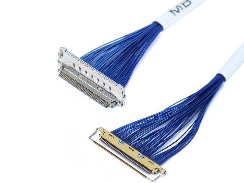
In LVDS (Low Voltage Differential Signaling) display systems, Micro-coaxial Cable (also referred to as Micro Coax Cable) stands out as an optimal solution for high-resolution, high-reliability signal transmission. Designed to meet the str.
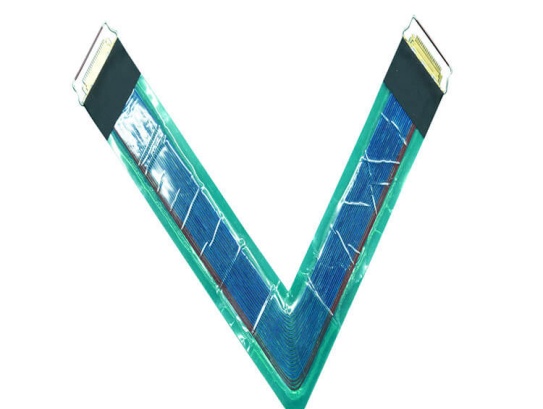
Contact Us Micro Coaxial Cable factory-(FRS).


Feel free to reach out to us for any inquiries or orders

Call Us

Have a question? Give us a call!

+861881875005

Email Us

Send us an email and we'll get back to you soon.

sales@custom-cable-assemblies.com
       
Home Products Contact