Why this cable matters now
PCI Express 6.0 raises the per‑lane signaling rate to 64 GT/susing PAM4modulation and lightweight FEC/FLIT, which doubles effective bandwidth while demanding much tighter channel and connector performance than PCIe 5.0. For system designers, this means that conventional PCB traces and legacy interconnects quickly run out of margin, especially in dense, high‑density boards and mezzanine cards. A purpose‑built 64 Gbps micro‑coaxialinterconnect—with controlled impedance, low loss, and excellent EMI containment—helps preserve eye opening, reduce jitter/BER, and enable reliable high‑speed links where board real estate is at a premium
How PCIe Gen6 changes interconnect requirements
- •Modulation and coding: PAM4places four voltage levels in each symbol interval, halving the noise margin versus NRZ. To close the link reliably, Gen6 adds a low‑latency FECplus CRC, and moves to fixed‑size FLITunits that improve efficiency and reduce overhead. These changes make the physical layer far more sensitive to impedance discontinuities, insertion loss, and crosstalk.
- •Reach and topology: With standard FR4 channels, Gen6 often requires signal conditioning (e.g., retimers) beyond a few inches. Industry work shows that with advanced SerDes and optimized passive cables, PCIe Gen6 copper links beyond 3–4 mare achievable in specific demonstrations, but such lengths are atypical for most system designs and need careful characterization. For structured cabling inside and between systems, CopprLinkinternal/external cable specs now define 32/64 GT/soperation over standardized connectors, with typical reaches of ~1 m (internal)and ~2 m (external)for mainstream deployments2410.
What makes a micro‑coax cable “Gen6‑ready”
- •Impedance and return loss: Tightly controlled differential impedance (typically 100 Ω) with excellent return loss across the Nyquist band is non‑negotiable for PAM4. Even small deviations can cause eye closure at 64 Gbps.
- •Insertion loss and material choices: Low‑loss dielectrics and high‑conductivity shields minimize IL and resistive losses. Component vendors’ Gen6‑rated micro‑coax assemblies are specified up to 16 GHzanalog bandwidth, which comfortably supports 64 Gbps PAM4when paired with good connectors and layout.
- •Shielding and EMI: Full 360° shielding (e.g., ZenShield®) and robust connector grounding are critical to contain EMI and prevent coupled noise from degrading neighboring high‑speed pairs.
- •Mechanical reliability: Micro‑coax demands disciplined bend and flex control. As a rule of thumb, maintain a minimum bending radius of ≥ 6× the cable outer diameterand avoid unsupported twisting to prevent impedance and structural degradation over life112.
Connector and form‑factor selection
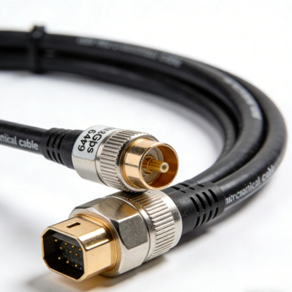
- •Match the ecosystem: For internal board‑to‑board and mezzanine links targeting PCIe Gen6 64 Gbps, choose connectors validated for the desired data rate and proven in high‑speed designs. Examples include I‑PEX CABLINE®‑CA IIP PLUSand CABLINE®‑CAP, which are specified for 64 Gbps/lane PAM4with 0.4 mmpitch and support for AWG 36–38micro‑coax. These connectors offer full shielding and mechanical locks for reliable high‑density routing.
- •Density vs. reach: Finer pitches (e.g., 0.25–0.3 mm) enable higher pin counts in smaller footprints but can reduce mechanical tolerance and increase routing difficulty; use the largest pitch and widest allowable cable that your space and loss budget permit.
- •Pin assignment and routing: Use 1‑N(straight) or 1‑1(mirror) pin assignments to simplify breakout and length matching. Keep differential pairs length‑matched within tight tolerances and avoid stubs; bring signals onto the connector field with minimal via transitions to limit return‑path discontinuities112.
Design checklist and trade‑offs for 64 Gbps micro‑coax PCIe Gen6 links
- •Channel budget first: Start with your system’s loss budget at 32 GHz(the Nyquist frequency for 64 Gbps PAM4) and allocate margin for connectors, vias, board traces, and cable. Remember that loss scales with frequency, so a cable that looks “good” at 16 GHz may still be marginal at 32 GHz.
- •Length planning: If you need more than a few inches of mezzanine reach, consider high‑quality micro‑coax with the best‑available loss tangent and shielding, but validate with channel simulation and measurements. For structured deployments, leverage CopprLink‑compliant internal/external assemblies where ~1 m / ~2 mare typical targets.
- •Equalization and FEC: Gen6’s FECprovides net BER improvement but does not replace good analog design. Ensure your controller/PHY offers adaptive equalization suited to your channel; in difficult channels, plan for retimersor active copper solutions to restore margin.
- •EMI/EMC: Route differential pairs as tightly coupled as possible, maintain consistent reference planes, and use connectors and cable with full shieldingand robust ground returns. Pay special attention to dense mezzanine areas where coupling between adjacent high‑speed pairs can erode eye height.
- •Assembly and handling: Use controlled‑impedance tooling and strain‑relief fixtures. Follow the manufacturer’s minimum bend radius and avoid routing sharp corners or routing the same micro‑coax bundle adjacent to power or clock lines without separation. For mission‑critical links, perform TDR/TDT, eye‑diagram, and BER testing across temperature and voltage corners1210.
Real‑world examples and practical expectations
- •Interposer/mezzanine links in GPUs, accelerators, and storage controllers often benefit most from micro‑coax: the connectors and cables keep the signal path short, reduce via stubs, and provide excellent EMI control in dense assemblies. In space‑constrained products (e.g., handheld or embedded AI), micro‑coax also simplifies routing while preserving high‑speed margins.
- •For longer reaches or rack‑to‑rack connections, structured CopprLinkcopper cables (internal ~1 m, external ~2 m) offer a standards‑based path to 64 GT/swith predictable reach and connector commonality. In exploratory demonstrations, optimized Gen6 copper DACs have exceeded 3–4 m, but these are application‑specific and require careful SI validation2412.
Component examples you can start with
- •Connectors: I‑PEX CABLINE®‑CA IIP PLUS(0.4 mm pitch, up to 60 pins, 64 Gbps/lane PAM4, micro‑coax AWG 36–38) and CABLINE®‑CAP(0.4 mm pitch, up to 50 pins, 64 Gbps/lane PAM4, micro‑coax AWG 38). Both support full shielding and mechanical locks for robust high‑density interconnects. Pair with your preferred low‑loss micro‑coax and follow the vendor’s layout/assembly guidelines for optimal results