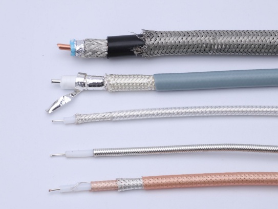
Definition and structure
An EMI shielding micro coaxial cable is a miniaturized coaxial interconnect optimized for high‑speed, high‑integrity signal paths in electrically noisy industrial environments. It comprises a central conductor, a precision dielectric, a conductive shield, and a protective jacket. Typical outer diameters range from about 0.22 mm to 1.32 mm, with many industrial designs using 0.3–0.5 mmto enable dense routing inside robot joints and small enclosures. Common dielectrics include PTFEand FEPfor stable electrical performance and flexibility; shields are typically a combination of braid and foil to maximize coverage, and the outer jacket may use PURor fluoropolymers for mechanical and chemical resistance. In robotics, these characteristics allow reliable high‑bandwidth links—such as MIPI CSIor LVDScamera interfaces—inside compact, moving assemblies.
Why robots need micro coax with EMI shielding
Industrial robots concentrate high‑current drives, fast switching power electronics, and dense control electronics in close proximity to high‑speed sensor and vision links. Without effective EMI control, cables can act as both antennas and conduits for interference, leading to image noise, data errors, or intermittent faults. Micro coax addresses this by providing each high‑speed channel with its own controlled‑impedance, shielded path that minimizes both ingress and egress of electromagnetic energy. This is particularly critical for multi‑gigabit image links in 4K/8Kvision systems and high‑resolution industrial cameras, where even small impedance mismatches or shield discontinuities can cause visible artifacts or EMC compliance failures.
How it works principles of EMI shielding and signal integrity
- Shielding layers: A dual shield—typically aluminum foil plus tinned copper braid—gives broadband EMI suppression. The foil efficiently attenuates higher‑frequency components, while the braid improves low‑frequency coverage and mechanical robustness. High‑quality constructions often target ≥85%shield coverage and maintain continuous shielding through the connector to prevent leakage paths. Grounding the shield at both ends (with care to avoid ground loops) provides a low‑impedance return for interference currents.
- Controlled impedance and differential signaling: Each micro coax is engineered to a precise characteristic impedance, commonly 45 Ωor 50 Ω, to match the source and load. This minimizes reflections and preserves eye diagrams at multi‑gigabit data rates. In high‑speed image links, preserving impedance continuity across the entire channel—cable, connector, and PCB—is as important as the cable itself.
- Low‑loss dielectrics and conductor geometry: Materials such as PTFE/FEPreduce dielectric loss, while finely controlled conductor dimensions and spacing maintain consistent impedance and reduce high‑frequency attenuation. The result is a compact interconnect that supports multi‑Gbpslinks with low jitter and low bit‑error rates.
- Mechanical flexibility and reliability: In robotic joints, cables undergo millions of dynamic bends. Micro coax leverages fine‑strand conductors, optimized lay lengths, and flexible jackets to achieve small bend radii and long flex lives, enabling reliable high‑speed links in moving assemblies without sacrificing signal quality.
Where it is used in industrial robots
- Joint and wrist internal links: High‑resolution camera/force/temperature/proximitysensors and high‑speed control links benefit from micro coax’s density and EMI resilience in confined, high‑flex environments.
- High‑speed vision systems: For MIPI CSI/LVDSor proprietary high‑bandwidth camera interfaces, micro coax provides per‑lane shielding and impedance control, enabling 4K/8Kimaging with reduced crosstalk and EMI.
- Small rotating assemblies and end‑effectors: Compact, shielded links are ideal where space is at a premium and continuous rotation or tight routing is required.
- Dynamic cable tracks and drag chains: In high‑flex, long‑travel applications, shielded micro coax assemblies with PURjackets and optimized bend radii are used to maintain signal integrity under millions of cycles.
How to choose the right EMI shielding micro coax for your robot
- Target data rate and interface: Match the cable’s bandwidth and impedance to the system (e.g., MIPI CSI/LVDS, proprietary high‑speed links). For very high data rates, ensure the vendor’s insertion loss and return‑loss data support your required link margin.
- Shielding architecture: Prefer dual‑shield (foil + braid)with high coverage and robust connector‑to‑cable shielding continuity. Verify shield termination and grounding strategy to suppress both emission and susceptibility.
- Mechanical demands: Define allowable bend radius, flex life, and environmental ratings (temperature, oil, abrasion). Choose PURor fluoropolymer jackets for demanding industrial environments; ensure the selected construction meets your cycle life and flex‑fatigue targets.
- Length and routing: Keep high‑speed runs as short as practical and away from high‑current switching nodes. Maintain consistent reference planes and consider strain relief at both connector and cable exit points to avoid shield discontinuities under load.
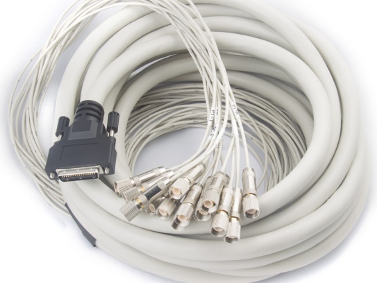
- Connector and termination: Use high‑shielding miniature connectors (e.g., micro‑coax variants like I‑PEX) with well‑engineered backshells and ground contacts. Ensure the shield is continuous from cable to connector housing, and that the solder or crimp transitions do not create impedance or shielding gaps.
Engineering best practices to maximize EMI performance
- Impedance and length control: Control skewacross differential pairs and match lengths to timing budgets. Mismatches cause reflections and radiated emissions; precise length control is a primary lever for EMI reduction.
- Grounding and loop control: Bond shields to chassis ground at one defined point (or use a hybrid scheme with care), and avoid creating ground loops. Star grounding at the controller helps contain interference currents.
- Separation and isolation: Route high‑speed micro coax away from power and clock lines. Use metal shields, ground planes, or absorptive materials at cable entry points to suppress coupling.
- Pre‑compliance and iteration: Perform early EMC pre‑scans and channel analysis (eye diagram, BER) during prototyping. If EMI or SI issues arise, adjust shield coverage, routing, or connector grounding before finalizing the harness.
Common pitfalls and how to avoid them
- Insufficient shield coverage or broken continuity at connectors leads to leakage and EMI failures. Use connectors with full metal shells and verify shield transfer with a continuity or shielding effectiveness test.
- Over‑tight bend radii or insufficient flex life cause broken conductors and intermittent opens. Respect the manufacturer’s bend radius and validate with accelerated life testing in your application’s duty cycle.
- Impedance mismatch and excessive length degrade eye opening and increase emissions. Control geometry, keep runs short, and verify with VNA/S‑parameter measurements.
- Mixing shield types indiscriminately: Understand that foilfavors high‑frequency attenuation while braidadds low‑frequency coverage and durability—use them in combination for broadband performance.
Materials and construction parameters that matter
- Conductor: High‑purity, high‑conductivity copper (or copper alloy) with fine stranding for flexibility and skin‑effect performance at high frequencies.
- Dielectric: PTFE/FEPor equivalent low‑loss materials maintain stable impedance and reduce insertion loss across temperature and frequency.
- Shield: Dual‑layer (foil + braid) with high coverage and robust coverage at connector transitions; ensure 360° shield contact in the connector backshell.
- Jacket: PURfor oil, abrasion, and flex resistance; fluoropolymers for high temperature and chemical environments. Match the jacket to the robot’s environmental and mechanical profile.
- Dimensional control: Tight control of conductor, dielectric, and shield geometry ensures consistent 45/50 Ωimpedance and predictable SI/EMI behavior across production lots.
Future trends and what to watch
- Higher bandwidth vision links: As resolutions and frame rates increase, expect continued demand for micro coax solutions supporting >10 Gbpsper lane with even better shielding and skew control.
- Integrated multi‑function cables: Hybrid designs that combine power, high‑speed data, and even fiber in compact assemblies are emerging to reduce harness complexity in next‑gen robots.
- Advanced materials and processes: Higher‑coverage shields, lower‑loss dielectrics, and refined termination methods will further improve EMI performance and flex life in compact, high‑cycle robotic systems.