
Micro Coaxial Cable-Micro Coaxial Cable factory-(FRS)-FRS
Critical Parameters:
Phase Stability: <1° variation per 90° bend at 28 GHz (n257 band).
Insertion Loss: <0.2 dB/cm at 39 GHz (n260 band).
Case Study: Ericsson’s AIR 6488 antenna uses 1.2mm cables with a 5× OD bend radius (6mm), achieving ±2° phase consistency across 64 channels.
B. mmWave FR2 Deployment (24–52 GHz)
At mmWave frequencies, even minor impedance mismatches from bending cause signal reflections and VSWR degradation.
Bend Radius (mm) VSWR at 28 GHz Insertion Loss (dB/m)
10 (8× OD) 1.3:1 1.2
6 (5× OD) 1.5:1 2.0
4 (3× OD) 2.1:1 4.5 (unusable)
Data for 1.25mm OD cable with ePTFE dielectric.
Dynamic Bend Radius: 3mm (2.4× OD) for 1.25mm cables.
Materials:
Conductor: Multi-stranded silver-plated copper.
Dielectric: Liquid crystal polymer (LCP) for low loss (tan δ <0.002).
Shield: Dual-layer helical foil + 95% braid coverage.
B. mmWave Antenna Modules
Apple’s iPhone 15 Pro uses 0.8mm cables to connect Qualcomm’s X70 modem to mmWave antenna arrays.
Bend Radius: 4mm (5× OD) to minimize loss at 28/39 GHz.
Shielding Effectiveness: >100 dB to suppress interference from nearby 5G/LTE signals.
Static Bend Requirements:
MBR: 5× OD (e.g., 1.6mm cable → 8mm radius).
Temperature Range: -40°C to +85°C (outdoor-rated LDPE jackets).
B. Distributed Antenna Systems (DAS)
In stadiums and airports, 1.85mm cables with 10× OD bends maintain <1.8:1 VSWR up to 6 GHz for multi-band signals (LTE/5G sub-6).
Typical Use: Near connectors or PCB interfaces.
Reduction in Loss: 30–50% at 28 GHz compared to unsleeved bends.
C. Simulation-Driven Routing
Finite Element Analysis (FEA) tools like ANSYS HFSS predict bend-induced losses and optimize cable paths:
Output: Ideal routing angles and clamp positions to avoid resonance hotspots.
B. Solution
Cable: 1.6mm OD, LCP dielectric, with corrugated copper-tin shield.
Bend Radius: 10mm (6.25× OD).
Result: Insertion loss reduced to 0.8 dB/m, meeting 3GPP TR 38.901 requirements.
Target: 4× OD bend radius at 140 GHz (D-band).
B. UAV-Based Mobile Networks
Drone-mounted base stations use lightweight 1.0mm cables with 8× OD bends to survive vibration (MIL-STD-810H).
C. 3D-Printed Cable Traces
Additive manufacturing enables custom cable channels that enforce optimal bend radii in compact devices.
Our factory offers high-quality products at competitive prices
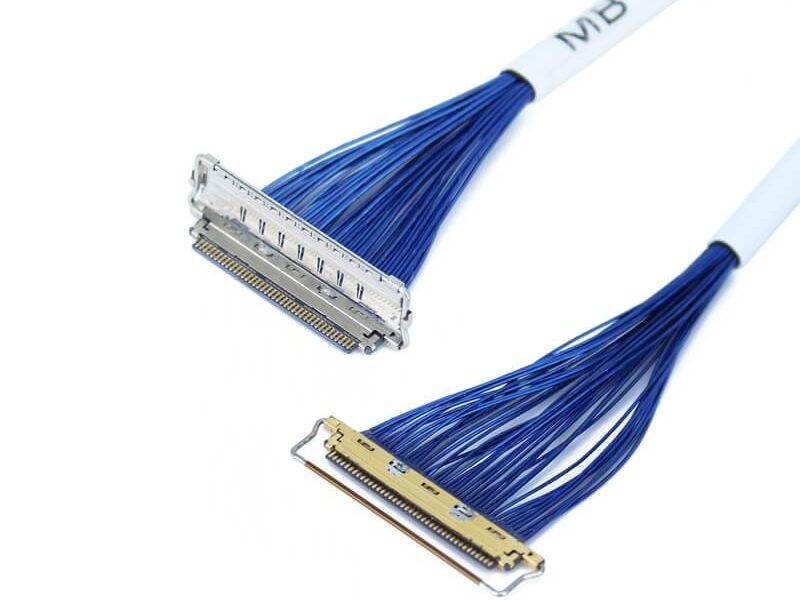
In LVDS (Low Voltage Differential Signaling) display systems, Micro-coaxial Cable (also referred to as Micro Coax Cable) stands out as an optimal solution for high-resolution, high-reliability signal transmission. Designed to meet the str.

KEL’s Micro Coaxial Cable solutions are at the forefront of modern electronic connectivity, offering exceptional performance in high-speed data transmission, miniaturization, and reliability. These connectors are integral to various.
Feel free to reach out to us for any inquiries or orders