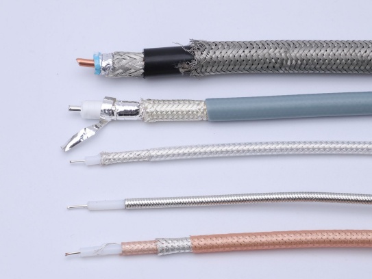
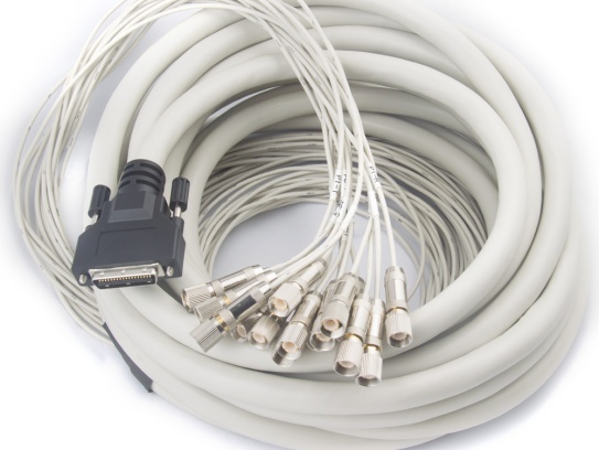
Coaxial cable assemblies are the backbone of critical communication and data transmission systems across industries such as telecommunications, aerospace, automotive, and industrial manufacturing. The connector, as the interface that ensures seamless signal transfer, is often the weakest link in these assemblies. Issues like signal degradation, intermittent connectivity, or complete failure can stem from improper installation, environmental damage, wear and tear, or manufacturing defects in connectors. For engineers, technicians, and maintenance professionals, quickly diagnosing and resolving these problems is essential to minimize downtime, reduce costs, and maintain system performance. In this guide, we’ll break down step-by-step troubleshooting methods for the most common coaxial connector issues, paired with practical tips to prevent future failures.
1. Understand the Common Connector Issues in Coaxial Assemblies
Before diving into troubleshooting, it’s critical to recognize the telltale signs of connector-related problems. The most frequent issues include:
- Signal Attenuation (Loss): Reduced signal strength, leading to poor data transmission or dropped communications.
- Intermittent Connectivity: Signal cuts in and out, often triggered by movement or vibration.
- Reflected Power (VSWR Mismatch): Signals bouncing back from the connector, causing interference and reduced efficiency.
- Physical Damage: Bent pins, cracked housings, or corrosion on contact surfaces.
- Loose Connections: The connector fails to lock securely, leading to signal leakage.
These issues can arise from various root causes: improper crimping or soldering during assembly, exposure to extreme temperatures or moisture, dust/debris buildup, or simply aging components. By linking symptoms to potential causes, you can streamline the troubleshooting process.
2. Pre-Troubleshooting Preparation: Tools and Safety
Effective troubleshooting requires the right tools and adherence to safety protocols. Gather the following equipment before starting:
- Vector Network Analyzer (VNA) or Cable and Antenna Analyzer: To measure VSWR (Voltage Standing Wave Ratio), return loss, and insertion loss—key metrics for identifying signal mismatches.
- Multimeter: To check for continuity and short circuits between the center conductor and shield.
- Connector Cleaning Kit: Includes lint-free wipes, isopropyl alcohol (90%+ purity), and a small brush (e.g., nylon bristle) for removing debris and corrosion.
- Crimp Tool or Soldering Iron: For repairing or reterminating connectors (ensure the tool matches the connector type, e.g., SMA, BNC, N-type).
- Torque Wrench: To ensure proper tightening (over-tightening can damage threads; under-tightening causes loose connections).
- Safety Gear: Anti-static wristband, gloves, and eye protection (especially when working with soldering or sharp components).
Always disconnect power from the system before handling connectors to avoid electrical shock or further damage to equipment.
3. Step-by-Step Troubleshooting Process
Step 1: Visual Inspection – Identify Obvious Damage
Start with a thorough visual check of the connector and surrounding cable. Look for:
- Physical Wear: Cracked or broken connector housings, bent center pins, or damaged threads (common in threaded connectors like N-type or SMA).
- Corrosion: Green/white oxidation on metal contacts (caused by moisture, saltwater, or humidity) or blackening from heat.
- Cable Damage: Kinks, cuts, or fraying near the connector—this can expose the shield or center conductor, leading to signal leakage.
- Debris Buildup: Dust, dirt, or foreign particles in the connector socket (especially in environments with high contamination).
Action: If corrosion or debris is present, clean the connector immediately (see Step 2). For cracked housings, bent pins, or severe cable damage, replace the connector or the entire assembly.
Step 2: Clean the Connector – Eliminate Contamination
Contamination is one of the leading causes of connector failure. Even small amounts of dust or corrosion can disrupt signal flow. Follow these cleaning steps:
- Disconnect the connector from the device or cable assembly.
- Dampen a lint-free wipe with isopropyl alcohol (avoid soaking the wipe—excess liquid can seep into the connector).
- Gently wipe the center conductor and outer contact surfaces. For hard-to-reach areas, use a small nylon brush to remove debris.
- Dry the connector thoroughly with a clean, dry wipe (moisture can cause corrosion over time).
- Inspect the connector again to ensure all contamination is removed.
Note: Never use abrasive materials (e.g., sandpaper, steel wool) or harsh chemicals—these can scratch contact surfaces and worsen signal loss.
Step 3: Check Continuity and Short Circuits
A multimeter can quickly identify electrical issues like broken conductors or short circuits between the center pin and shield.
- Set the multimeter to the continuity mode (symbol: sound wave or “CONT”).
- Touch one probe to the center conductor of the connector and the other to the center conductor of the opposite end (for a cable assembly). A beep indicates continuity—no beep means the center conductor is broken.
- Next, check for shorts: Touch one probe to the center conductor and the other to the outer shield. No beep is normal (the center conductor and shield should be isolated). A beep indicates a short circuit, which may be caused by a damaged cable or improper termination.
Action: If there’s no continuity or a short circuit, the cable or connector needs to be replaced or reterminated.
Step 4: Test Signal Performance with a VNA
For issues like signal attenuation or VSWR mismatch, a VNA is the most reliable tool. It measures how well the connector transmits signals and identifies reflections.
- Calibrate the VNA according to the manufacturer’s instructions (calibration ensures accurate readings).
- Connect the coaxial assembly to the VNA’s test ports.
- Measure VSWR: A VSWR reading of 1.5:1 or lower is ideal. Readings above 2:1 indicate a significant mismatch, which can be caused by:
- Loose or damaged connectors.
- Improperly terminated cables (e.g., incorrect crimping, exposed shield strands).
- Connector contact wear or corrosion.
- Measure insertion loss: Excessive loss (beyond the cable’s specified limits) often points to a faulty connector or poor termination.
Action: If VSWR or insertion loss is outside acceptable ranges, recheck the connector’s fit (ensure it’s fully seated and tightened) or reterminate the connector.
Step 5: Verify Proper Installation and Fit
Many connector issues stem from improper installation. Even if the connector is new, incorrect assembly can lead to failure:
- Threaded Connectors (N-type, SMA): Use a torque wrench to tighten the connector to the manufacturer’s recommended torque (typically 8–12 in-lbs for SMA, 20–30 in-lbs for N-type). Over-tightening can strip threads or damage the connector’s internal components; under-tightening causes loose connections.
- Crimped Connectors: Ensure the crimp tool is compatible with the connector and cable size. A weak crimp can cause intermittent connectivity, while an over-crimp can damage the center conductor or shield.
- Snap-on Connectors (BNC): Verify that the connector snaps into place securely. If it’s loose, check for damage to the locking mechanism or mating port.
Action: If installation is the issue, reterminate the connector using the correct tools and follow the manufacturer’s assembly guidelines.
Step 6: Test in Real-World Conditions
Sometimes, issues only manifest under specific conditions (e.g., vibration, temperature changes). After resolving apparent problems:
- Reconnect the assembly to the system and run operational tests.
- Simulate environmental stress (e.g., gentle movement, temperature cycles) to check for intermittent connectivity.
- Monitor signal performance over time to ensure the issue is fully resolved.
4. Preventive Maintenance Tips to Avoid Connector Issues
Troubleshooting is reactive—preventive maintenance reduces the likelihood of connector failures in the first place:
- Regular Cleaning: Schedule periodic cleaning of connectors, especially in harsh environments (e.g., outdoor telecom towers, industrial facilities with dust or moisture).
- Proper Storage: Store unused coaxial assemblies in a dry, clean environment. Use connector caps to protect contact surfaces from debris and corrosion.
- Use High-Quality Components: Low-quality connectors are more prone to wear, corrosion, and poor termination. Invest in connectors that meet industry standards (e.g., MIL-STD, IEC).
- Train Personnel: Ensure technicians are trained in proper connector installation, crimping, and soldering techniques.
- Environmental Protection: Use weatherproof connectors for outdoor applications and consider protective boots or enclosures to shield connectors from moisture, dust, and physical damage.
5. When to Replace a Connector or Cable Assembly
Not all issues can be fixed with troubleshooting. Replace the connector or entire assembly if:
- The connector housing is cracked or the center pin is bent beyond repair.
- Corrosion has penetrated the internal components (visible as discoloration or pitting).
- Retermination attempts fail to resolve signal issues (e.g., VSWR remains high).
- The cable shows signs of irreparable damage (e.g., frayed shield, broken center conductor).
- The connector has exceeded its service life (typical for high-cycle applications or harsh environments).
Trust FRS for Reliable Coaxial Cable Assemblies
Even with the best troubleshooting practices, the foundation of a trouble-free system lies in high-quality components. FRS Brand Factory specializes in manufacturing premium coaxial cable assemblies designed to minimize connector-related issues from the start. Our connectors are precision-engineered to meet strict industry standards, with features like gold-plated contacts for corrosion resistance, robust housings for mechanical durability, and consistent termination processes that ensure optimal signal integrity.
Every FRS coaxial assembly undergoes rigorous testing—including VSWR, insertion loss, and environmental stress tests—to guarantee performance in demanding applications, from aerospace to industrial automation. Whether you need standard configurations or custom assemblies tailored to your specific needs, FRS delivers reliability you can count on, reducing downtime and maintenance costs for your operations.
For systems that demand uncompromised connectivity, choose FRS coaxial cable assemblies—where quality craftsmanship meets engineering excellence. Contact FRS today to learn how our products can enhance the performance and longevity of your critical systems.